
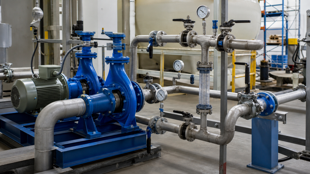
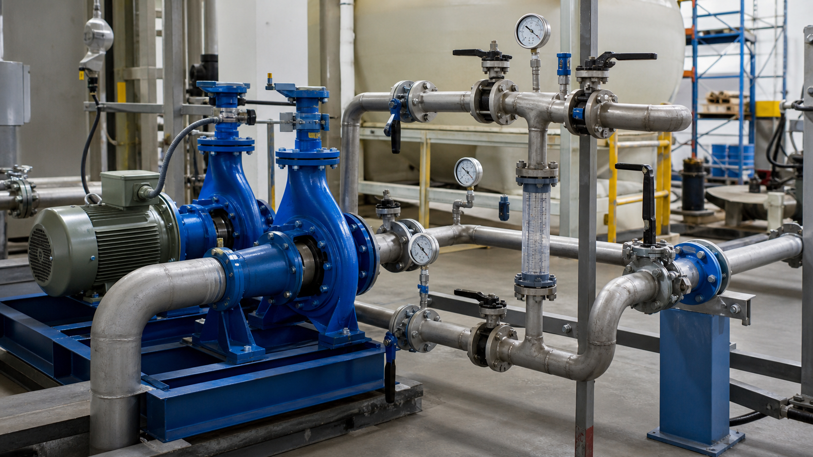
A water distribution system reaches full capacity at 500 gpm but cannot lift water 180 feet to the elevated storage tank; a single pump delivers 120 feet of head at that flow rate. An industrial cooling plant delivers 150 feet of head but cannot meet the 900 gpm peak during summer operations; a single pump provides only 450 gpm at the system resistance. Install the same model pumps in series for the first case—discharge of pump one feeds suction of pump two—and head doubles at every flow rate. Install them in parallel for the second case—both suction lines draw from the same header and both discharge lines merge—and flow capacity doubles at every head. The arrangement you choose determines which hydraulic dimension you multiply.
Series and parallel pump operation each solve a specific hydraulic constraint. Series configuration adds the head of each pump at a given flow rate, raising the combined curve vertically. Parallel configuration adds the flow rate of each pump at a given head, extending the combined curve horizontally. The system curve—representing friction, elevation, and pressure requirement—intersects the combined pump curve at the actual operating point. If you need more pressure or elevation, pumps in series deliver it. If you need more flow through an existing system, pumps in parallel provide it. The decision hinges on whether total dynamic head or flow rate is the limiting factor.
الوجبات الرئيسية
- Series pumps add head at constant flow; the combined curve stacks vertically and intersects the system curve at higher head than a single pump can produce.
- Parallel pumps add flow at constant head; the combined curve extends horizontally and intersects the system curve at higher flow than a single pump can deliver.
- The system curve slope determines the actual gain; flat systems (low friction) gain more flow in parallel, while steep systems (high static head or friction) gain more head in series.
- Unequal pumps require individual curve analysis; the smaller pump may operate off its best efficiency point or at reduced flow when paired with a larger unit.
- Check valves, sequencing controls, and minimum-flow recirculation are essential for stable operation in both arrangements, especially when pumps start and stop independently.
- One-pump-out operation must be verified against the system curve; a single pump may not meet minimum flow or head when the second unit fails or is offline for maintenance.
Series and Parallel Solve Different Hydraulic Constraints
Pumps in series multiply head. Each impeller adds energy to the same stream of liquid. The discharge of the first pump becomes the suction of the second pump, and the second pump lifts the already-pressurized liquid to a higher level. Total head equals the sum of individual pump heads at the flow rate where the combined curve crosses the system curve. Use series configuration when system resistance or static lift exceeds the shutoff head of a single pump.
Series applications include booster stations with extreme elevation changes, multistage vertical turbine pumps in deep wells, and fire protection systems where discharge pressure requirements exceed single-stage capability. Each stage or pump in the series string contributes incremental head. If the first pump delivers 100 feet and the second delivers 100 feet at the operating flow rate, the combined output is 200 feet at that flow.
Pumps in parallel multiply flow. Each pump draws from a common suction header and discharges into a common discharge header. The liquid divides between the pumps, and each pump moves a portion of the total. Total flow equals the sum of individual pump flows at the head where the combined curve crosses the system curve. Use parallel configuration when a single pump cannot deliver the required flow rate against the system resistance.
Parallel applications include municipal water treatment plants with variable demand, irrigation stations serving large acreage, and cooling systems where peak flow occurs during limited periods. Two identical pumps in parallel deliver twice the flow of a single pump only in a zero-resistance system; actual gain depends on the system curve slope.
How to Build the Combined Series Curve
Start with the published H-Q curve for one pump. For each flow rate on the horizontal axis, read the corresponding head on the vertical axis. Double the head value and plot the new point at the same flow rate. Repeat for enough flow points to define the curve shape from shutoff to runout. The resulting combined curve rises vertically above the single-pump curve.
Example: A centrifugal pump delivers 80 feet at 200 gpm, 70 feet at 300 gpm, and 50 feet at 400 gpm. Two identical pumps in series deliver 160 feet at 200 gpm, 140 feet at 300 gpm, and 100 feet at 400 gpm. Plot these points and draw the combined curve. The shutoff head also doubles; if one pump shuts off at 85 feet, two pumps shut off at 170 feet.
For unequal pumps, add the individual heads at each flow rate. A 100-foot pump and a 60-foot pump together deliver 160 feet at the flow where both curves report those values. The combined curve is limited by the smaller pump’s maximum flow; beyond that point, only the larger pump contributes. This mismatch often forces the smaller pump to operate away from its best efficiency point (BEP), increasing wear and power consumption.
The series combined curve intersects the system curve at the operating point. If your system curve requires 140 feet at 250 gpm, and the series curve delivers exactly 140 feet at 250 gpm, that intersection defines the duty point. Check that both individual pumps operate within their published operating envelopes at that flow. Verify that net positive suction head available (NPSHa) at each pump suction exceeds the required NPSHr; consult the pump manufacturer’s data sheet for the required margin based on pump design and application conditions.
How to Build the Combined Parallel Curve
Start with the same published H-Q curve. For each head value on the vertical axis, read the corresponding flow rate on the horizontal axis. Double the flow value and plot the new point at the same head. Repeat for enough head points to define the curve from shutoff to runout. The resulting combined curve extends horizontally to the right of the single-pump curve.
Example: The same centrifugal pump delivers 200 gpm at 80 feet, 300 gpm at 70 feet, and 400 gpm at 50 feet. Two identical pumps in parallel deliver 400 gpm at 80 feet, 600 gpm at 70 feet, and 800 gpm at 50 feet. Plot these points and draw the combined curve. The shutoff head remains the same—85 feet—because both pumps contribute zero flow at shutoff.
For unequal pumps in parallel, add the individual flows at each head. A 300-gpm pump and a 200-gpm pump together deliver 500 gpm at the head where both curves report those individual flows. This approach requires careful attention to the drooping or rising shape of each curve. If one pump has a steeply drooping curve (head falls rapidly with increasing flow) and the other has a flat curve, the operating point may shift unpredictably as pumps cycle on and off.
The parallel combined curve intersects the system curve at the operating point. If your system curve requires 70 feet at 500 gpm, and the parallel curve delivers 70 feet at 500 gpm, that intersection defines the duty point. Flow divides between the pumps according to their individual resistances and curve shapes. In a perfectly balanced system with identical pumps, flow splits evenly. In practice, small differences in impeller wear, motor speed, or piping resistance cause unequal flow distribution. Install flow meters or balancing valves if precise distribution is required.
The System Curve Determines the Actual Gain
The system curve represents the relationship between flow rate and total dynamic head in your specific piping system. It includes static head (elevation change and pressure difference), friction head (pipe, fittings, valves), and velocity head (usually negligible in liquid systems). System curves are parabolic; head increases with the square of flow rate because friction loss is proportional to velocity squared.
In a flat system curve—low static head and low friction—parallel pumps deliver substantial flow gain. If the system curve rises gently, the parallel combined curve intersects it at nearly double the single-pump flow. Example: A system with 10 feet of static head and minimal friction requires 20 feet at 500 gpm for a single pump. Two pumps in parallel deliver nearly 1,000 gpm because the system curve has not risen much by the time flow doubles.
In a steep system curve—high static head or high friction—parallel pumps deliver modest flow gain. If the system curve rises steeply, the parallel combined curve intersects it at less than double the single-pump flow. Example: A system with 80 feet of static head requires 100 feet at 500 gpm for a single pump. Two pumps in parallel may deliver only 700 gpm because the system curve climbs to a higher head as flow increases, and each pump must work against that higher head. The interaction between pump curve and system curve governs the actual operating point.
Series pumps overcome steep system curves efficiently. If the system curve is dominated by elevation, the series combined curve intersects it at a much higher elevation than a single pump can reach. Series configuration adds head without fighting increased system resistance, because the same flow passes through both pumps.
Series pumps deliver minimal flow gain in any system. Total flow cannot exceed the maximum flow of the smaller pump. Series configuration increases pressure or lift, not capacity. If your system is flow-limited, install parallel pumps instead.
Identical versus Unequal Pumps
Identical pumps simplify series and parallel design. In series, each pump contributes equal head at the operating flow. In parallel, each pump contributes equal flow at the operating head. The combined curve is predictable, and each pump operates near its BEP if the system is properly sized. Maintenance and spare parts are standardized. Control logic is straightforward because both pumps respond identically to speed or throttling adjustments.
Unequal pumps introduce asymmetry. In series, the smaller pump may reach its maximum flow before the larger pump is fully loaded. The combined output is limited by the smaller pump’s capacity. If a 300-gpm pump is placed in series with a 500-gpm pump, total flow cannot exceed 300 gpm. The larger pump operates at part load, reducing efficiency and potentially causing recirculation or cavitation if it is far below BEP.
In parallel, the larger pump may carry a disproportionate share of the total flow. If a 300-gpm pump and a 500-gpm pump discharge into the same header, the 500-gpm unit will deliver more flow at any given head because its curve extends further to the right. The 300-gpm pump may operate near its runout point, leading to low efficiency, overloading, and overheating. Install discharge throttling valves or VFD speed control on the larger pump to balance the load if necessary.
Curve shape also matters. A drooping or unstable curve in parallel operation can cause one pump to reverse flow or oscillate as system pressure changes. Centrifugal pumps should have continuously rising head from runout to shutoff. If the curve is flat or has a hump, parallel operation becomes unstable; the operating point may jump between multiple intersections with the system curve. Review the manufacturer’s curve carefully before committing to parallel operation with pumps of different designs.
Check Valves, Sequencing, VFDs, and Minimum Flow
Check valves prevent reverse flow when one pump stops. In series, install a check valve on the discharge of each pump to prevent backflow from the downstream pump or system. In parallel, install a check valve on the discharge of each pump to prevent backflow from the common header when that pump is off. Without check valves, the running pump may drive reverse flow through the idle pump, spinning it backward and damaging the seal, bearings, or impeller.
Sequencing controls determine the order in which pumps start and stop. Alternating duty schedules (pump one leads on Monday, pump two leads on Tuesday) equalize runtime and wear. Lead-lag controls start the lead pump first; if flow or pressure demand exceeds the lead pump’s capacity, the lag pump starts automatically. If demand drops, the lag pump stops first, then the lead pump if demand continues to fall. This strategy minimizes energy consumption and keeps each pump within its efficient operating range.
VFDs allow continuous flow or pressure control. In parallel, vary pump speed to match demand without cycling pumps on and off. In series, reduce speed of both pumps proportionally to maintain flow balance. VFD control reduces energy consumption in variable-demand systems because power is proportional to speed cubed. However, VFDs add cost, complexity, and potential harmonic distortion. Evaluate whether the energy savings justify the investment and whether your electrical system can tolerate the harmonics.
Minimum flow recirculation protects pumps from operating at shutoff or near shutoff. When flow drops below the minimum continuous flow specified by the manufacturer, a recirculation line opens to return a portion of the discharge back to the suction tank or reservoir. This prevents overheating, cavitation, and seal damage. In series, the minimum flow requirement of the first pump may differ from the second; design recirculation for the most restrictive case. In parallel, each pump must maintain its own minimum flow, so the combined system may require a higher recirculation rate than a single pump.
Reliability and One-Pump-Out Operation
One-pump-out operation tests whether the system can function when one pump is offline for maintenance or failure. In parallel, the remaining pump must deliver sufficient flow at the system head to meet minimum process or safety requirements. Check the single-pump curve against the system curve. If the intersection point falls below the minimum acceptable flow, install a third pump or oversize the two pumps so that one alone meets the minimum.
In series, the remaining pump may not deliver sufficient head. If the system requires 150 feet and each pump delivers 80 feet alone, losing one pump leaves only 80 feet—potentially insufficient to overcome static elevation or pressure. Series systems often cannot operate on one pump unless the operating point is deliberately set low enough that a single pump reaches it. Consider this limitation during design. For critical applications, install a third pump in series or accept that the system will be down if one pump fails.
Redundancy improves availability but increases capital and operating costs. A two-pump parallel system with each pump sized for 60 percent of peak flow provides 120 percent capacity when both run and 60 percent when one fails. A three-pump system with each pump sized for 50 percent provides 150 percent capacity when all run and 100 percent when one fails. Evaluate the cost of downtime against the cost of the additional pump, piping, valves, controls, and floor space.
Maintenance access and spare parts inventory also affect reliability. Identical pumps allow a single spare rotor, seal kit, and bearing set to service any unit. Unequal pumps require separate inventories for each model. Parallel pumps can be isolated, drained, and serviced while the other pump continues to run. Series pumps require both units to be shut down simultaneously if the piping does not include isolation valves between stages. Plan maintenance shutdowns around production schedules and install isolation valves where continuous operation is required.
Decision Matrix for Series or Parallel
Use the following conditions to narrow your choice:
الحالة | سلسلة | موازي |
|---|---|---|
System head exceeds single-pump shutoff | Required | Not applicable |
System flow exceeds single-pump capacity | Not applicable | Required |
Static head is the dominant resistance | المفضلة | Less effective |
Friction head is the dominant resistance | Less effective | المفضلة |
System curve is steep | المفضلة | Limited flow gain |
System curve is flat | Limited head gain | المفضلة |
Demand varies widely over time | Consider VFD on series pumps | Lead-lag parallel with VFD |
One-pump-out operation must meet minimum duty | Often not possible | Possible if pumps are oversized |
Physical space is limited | Series in a single casing (multistage) | Parallel requires more floor area |
Pump curves have drooping or flat regions | مقبول | Avoid; may cause instability |
Walk through the decision process with your actual system curve and pump curves. Plot the combined curve and find the intersection. Verify that NPSHa exceeds NPSHr at that point. Check the power requirement against available motor and electrical capacity. Confirm that each pump operates between its minimum continuous flow and maximum flow at the duty point. If the operating point falls outside the published envelope, select a different pump model or reconsider the arrangement.
For existing installations, measure actual flow, pressure, and power to validate the current operating point. If performance is inadequate, determine whether the shortfall is in head or flow. If pressure is low, series may help. If flow is low, parallel may help. If both are low, the pumps may be undersized or worn, and the arrangement is not the primary issue. Inspect the impellers, wear rings, and mechanical seals for damage or clearance growth. Verify that suction piping is free of blockages, air pockets, or leaks that reduce NPSHa.
الأسئلة الشائعة
Can you mix different pump models in series or parallel?
Yes, but performance becomes harder to predict. In series, the combined head equals the sum of individual heads at the operating flow, but the smaller pump limits total flow. In parallel, the combined flow equals the sum of individual flows at the operating head, but curve shape differences can cause unequal load distribution and instability. Identical pumps simplify design, operation, and maintenance. Use dissimilar pumps only when space, budget, or existing equipment constraints require it, and verify the combined curve against the system curve before committing.
What happens if one pump fails in a parallel system?
The remaining pump continues to operate, but the duty point shifts. The system curve now intersects the single-pump curve instead of the combined parallel curve, resulting in lower flow and higher head on the remaining pump. Check that the new operating point stays within the pump’s envelope and meets minimum process requirements. If the single-pump duty point is too close to runout or shutoff, install a third pump or oversize the original pumps. The check valve on the failed pump prevents reverse flow and protects the idle unit from damage.
Do parallel pumps always split flow evenly?
No. Flow distribution depends on the resistance of each pump’s suction and discharge piping, impeller wear, motor speed variation, and curve shape. In a perfectly balanced system with identical pumps and symmetric piping, flow splits evenly. In practice, one pump may carry 55 percent and the other 45 percent. Small imbalances are acceptable and do not harm the pumps. Large imbalances indicate a blockage, cavitation, worn impeller, or incorrect valve position. Install flow meters if precise distribution is required, or accept the natural distribution if both pumps remain within their operating envelopes.
Can you control series or parallel pumps with a single VFD?
Yes, if both pumps are powered by a common VFD and mechanical coupling. This approach is common in multistage pumps where all impellers are on the same shaft and driven by one motor. For separate pumps, install one VFD per pump to allow independent speed control. Parallel pumps benefit from independent VFDs because you can modulate each pump’s contribution to match demand without cycling pumps on and off. Series pumps require synchronous speed changes to maintain flow balance, so a single VFD may suffice if the pumps share a common shaft or are mechanically coupled.
How do you calculate total power for series or parallel pumps?
In series, add the power consumed by each pump. Power equals flow times head times specific gravity divided by 3,960 times efficiency. Since flow is constant through both pumps and each pump contributes head, total power is the sum of individual powers. In parallel, add the power consumed by each pump. Flow divides between the pumps, but each pump works against the same head, so total power is again the sum. Always calculate power using the actual operating flow and head from the combined curve intersection with the system curve, not the nameplate values. Consult the motor manufacturer for appropriate service factor, starting torque capacity, and derating over time.
الخاتمة
The choice between pumps in series and pumps in parallel is a hydraulic decision. Series doubles head; parallel doubles flow in a zero-resistance system and delivers a smaller gain as system resistance increases. Plot your system curve, overlay the single-pump curve, then construct the combined series or parallel curve to see where each arrangement intersects your requirement. Verify that the operating point keeps both pumps within their published envelopes, that NPSHa exceeds NPSHr with the margin specified in the pump data sheet, and that power demand stays within motor and electrical capacity. Document the selection logic, combined curve, and control strategy before ordering equipment. For critical applications, simulate one-pump-out operation and confirm that the remaining pump meets minimum duty. Collect the actual pump curves, system head calculation, and electrical single-line diagram, and submit them to your pump supplier for final verification before installation.