
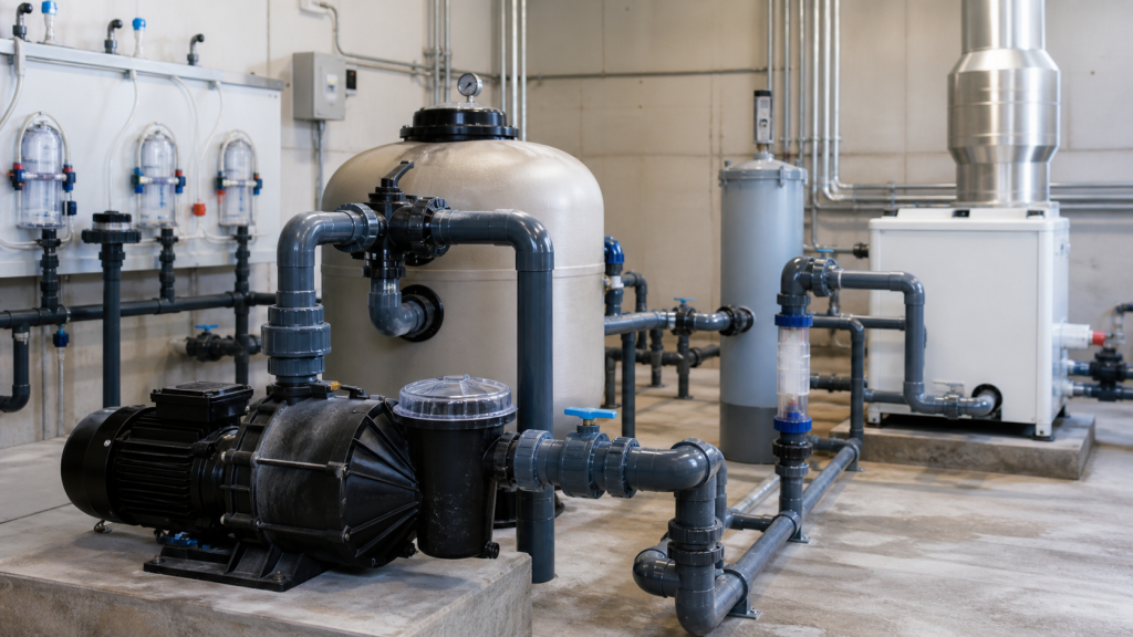
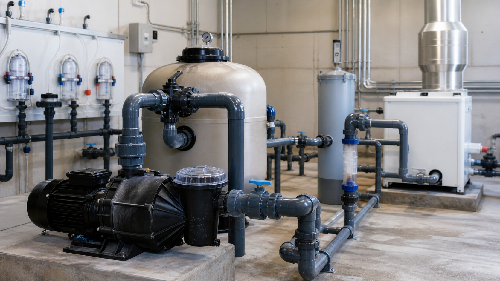
A 20,000-gallon commercial pool is calculated for 8-hour turnover at 42 GPM. The spreadsheet confirms the requirement, the pump nameplate lists 50 GPM at design speed, and the owner approved the quote. During operation, the skimmer barely pulls debris and the shallow end develops visible turbidity. A clamp-on ultrasonic flowmeter reads 28 GPM—one-third below target—and the discharge gauge shows 15 psi where the curve predicted 22 psi. The pump is running but the flow rate is not meeting circulation demand.
Pool pump flow rate is the volume of water moved per unit time, expressed in gallons per minute (GPM) or cubic meters per hour (m³/h). It must satisfy three requirements: turnover-based circulation, equipment minimum flow, and system hydraulic capacity. This article explains how to calculate target flow from pool volume and turnover, apply filter and heater constraints, measure actual delivered flow, and diagnose shortfalls without exceeding safe operating limits.
الوجبات الرئيسية
- Target flow is calculated from pool volume divided by desired turnover hours, then verified against filter, heater, chlorinator, and water-feature minimums.
- Actual flow depends on system head, not pump nameplate rating—measure with a flowmeter or derive from gauge readings and the pump curve.
- Filter pressure rise, heater differential, and chlorinator contact time set lower flow boundaries that may exceed the turnover calculation.
- Spa jets and water features create parallel demand paths that must be added to main circulation flow if served by the same pump.
- Variable-speed operation adjusts flow seasonally, but must maintain minimum filter velocity and equipment manufacturer limits at all setpoints.
- Flow shortfalls result from high system head, worn impellers, air leaks, or clogged strainers—diagnose with pressure and amperage data before increasing speed.
Flow Rate Is a Circulation Target, Not a Pump Label
Flow rate for a pool system is determined by the hydraulic requirement—how much water must circulate to maintain clarity, chemical distribution, and surface skimming—not by the pump’s maximum capacity. A 3/4 HP pool pump may deliver 62 GPM at zero head in an open test stand, but the same pump on a system with 40 feet of total dynamic head, suction lift, and a cartridge filter at mid-cycle pressure will deliver less. The duty point—the intersection of the pump curve and the system curve—sets actual flow.
Three numbers define the requirement:
- Turnover flow: Pool volume divided by target turnover time.
- Equipment minimum: The lowest flow at which the filter backwashes properly, the heater maintains outlet temperature without short-cycling, and the chlorinator achieves contact time.
- Feature flow: Additional GPM for spa jets, waterfalls, deck jets, or fountain nozzles when operated simultaneously with main circulation.
If these three values align and the system curve intersects the pump curve in the manufacturer’s recommended operating range, the design is hydraulically sound. If the turnover calculation is 40 GPM but the sand filter requires minimum face velocity for effective backwash per its datasheet, the system must be sized to the filter’s requirement. The pump curve must then deliver that flow at the actual system head, accounting for piping friction, elevation change, filter pressure drop, and valve losses.
Calculate Volume and Target Turnover Flow
Pool volume is computed from geometry. For rectangular pools, volume in gallons equals length (ft) × width (ft) × average depth (ft) × 7.48. For circular pools, use π × radius² × depth × 7.48. Irregular shapes require segmentation or digital takeoff. Always add the volume of attached spas, surge tanks, and balance tanks if they are part of the circulation path.
Turnover time is the number of hours required to pass the entire pool volume through the filter once. Residential pools typically target 8 to 12 hours; commercial pools and spas target shorter intervals depending on bather load and local health codes. Check the applicable code for minimum turnover rates in public facilities.
Turnover flow formula:
Q = V / (T × 60)
المكان:
- Q = flow rate (GPM)
- V = pool volume (gallons)
- T = turnover time (hours)
- 60 = conversion from hours to minutes
Worked example:
- Pool volume: 25,000 gallons
- Target turnover: 6 hours
- Q = 25,000 / (6 × 60) = 25,000 / 360 = 69.4 GPM
Round to 70 GPM as the baseline circulation requirement. This value is the minimum main circulation flow. It does not yet include equipment constraints or parallel feature demand.
Apply Filter, Heater, Chlorinator, and Feature Limits
Each piece of equipment introduces a minimum flow threshold below which it cannot perform its function.
Sand and media filters require adequate face velocity to suspend the bed during backwash. Consult the manufacturer’s data for the minimum GPM or GPM per square foot of filter area for your model. A filter’s effective backwash velocity depends on its diameter, bed depth, and media type—check the installation manual rather than applying a universal value.
Cartridge filters do not backwash but still require minimum flow for even distribution across the pleats. Check the manufacturer’s minimum GPM rating.
Heat exchangers and gas heaters specify minimum flow to prevent flame rollout, thermal stratification, and localized boiling. Consult the heater’s installation manual for the required GPM. If the heater is on the main circulation line, the system flow must meet that threshold. Undersized flow causes the heater to cycle on high-limit, reducing efficiency and shortening element life.
Salt chlorinators and chemical feeders depend on contact time. The cell or chamber must see the flow rate specified by the manufacturer to achieve rated chlorine production. Manufacturers publish a minimum and maximum GPM range for each model. Operating below the minimum reduces sanitizer output; operating above the maximum shortens cell life due to inadequate contact.
Waterfalls, deck jets, and spa jets add parallel demand. If the pool has a waterfall requiring a given GPM per the feature manufacturer’s specification and the main circulation is 70 GPM, the total pump flow is the sum of both if they run simultaneously. If the waterfall is served by a dedicated secondary pump, it does not affect the main circulation calculation.
Collect all equipment datasheets and compare the minimum flow against the turnover value. The controlling requirement is the highest of the set. Document this as the design flow rate before selecting the pump.
Separate Main Circulation from Spa and Water-Feature Demand
Pools with attached spas present three hydraulic configurations:
- Shared circulation, simultaneous operation: The pump must deliver main pool turnover plus spa turnover at the same time. Add the two flows.
- Shared circulation, valved isolation: The pump delivers pool flow when spa valves are closed and spa flow when pool valves are closed. Size for the higher of the two.
- Dedicated spa pump: The spa has its own pump, separate suction and return lines, and independent filtration. Main pool flow is unaffected.
For configuration 1, calculate spa flow from spa volume and the required turnover time:
- Spa volume: 500 gallons
- Spa turnover: 0.25 hours (15 minutes, as an example)
- Spa turnover flow = 500 / (0.25 × 60) = 33.3 GPM
- Main pool turnover: 70 GPM
- Combined system flow: 70 + 33 = 103 GPM
The pump must be rated for 103 GPM at system head. If the spa is isolated by valves during normal pool circulation, size for 70 GPM and accept reduced pool flow during spa-priority operation, or install a two-speed or variable-speed pump with a high-speed spa mode.
Water features follow the same logic. Review manufacturer specifications for all aesthetic and therapeutic features before finalizing the circulation design.
Measure Actual Flow and Read Pressure Evidence
Nameplate GPM is not delivered GPM. Measure actual flow using one of four methods:
Inline flowmeter: Magnetic or turbine flowmeters installed in the discharge pipe give continuous real-time measurement. Accuracy depends on meter calibration and installation per manufacturer instructions. Turbine meters are less expensive but sensitive to debris and air.
Clamp-on ultrasonic flowmeter: Non-invasive transducers measure transit time or Doppler shift through the pipe wall. Accuracy depends on correct pipe schedule, fluid properties, and transducer placement. Useful for field verification without cutting into the system.
Bucket-and-stopwatch test: For small systems, divert return flow into a 5-gallon bucket and time the fill. Divide volume by time to get GPM. Not practical for large commercial pools but effective for portable spa pumps.
Pressure-curve method: Measure suction and discharge pressure, calculate total dynamic head (TDH), and read flow from the pump curve at that head. This method requires an accurate curve and assumes the impeller is not worn, the volute is not eroded, and the motor is delivering rated speed.
For pressure-curve measurement:
TDH (ft) = (P_discharge – P_suction) × 2.31 / SG + Z_discharge – Z_suction
المكان:
- P_discharge, P_suction = gauge pressure (psig)
- SG = specific gravity (1.0 for freshwater)
- Z = elevation (ft)
- 2.31 = conversion factor from psi to feet of water
A discharge gauge reading 20 psig and a compound suction gauge reading 5 inches Hg vacuum (–2.5 psig) with negligible elevation change gives:
TDH = (20 – (–2.5)) × 2.31 = 22.5 × 2.31 = 52 ft
Locate 52 ft on the vertical axis of the pump curve and read horizontally to the curve intersection to find delivered flow.
Compare measured flow to design flow. A modest shortfall after one season may result from filter loading and strainer fouling. A larger variance indicates a hydraulic problem that must be diagnosed before the system fails to maintain water quality.
Diagnose a Flow Shortfall without Overspeeding the System
When actual flow is below target, operators instinctively increase pump speed or install a larger motor. This approach is wrong if the root cause is high system head, and dangerous if it pushes the pump beyond its maximum operating envelope.
Diagnose before adjusting:
Check strainer baskets and filter pressure: A clogged strainer basket can add significant head. A filter at end-of-cycle can add substantial pressure drop depending on filter type and loading. Clean or backwash both and remeasure. If flow recovers, the problem is maintenance, not sizing.
Inspect for air leaks on the suction side: Air entering through a loose pump lid, cracked suction fitting, or split hose reduces effective flow and causes the pump to lose prime intermittently. Seal all suction joints and retest.
Check impeller for wear or debris: Open the pump casing and inspect the impeller vanes. Calcium scale, sand, and leaf fragments reduce effective diameter. Chemical erosion in salt pools can thin the vanes. If the impeller diameter has been reduced substantially from the original casting, replace it.
Verify motor speed and voltage: Use a tachometer or strobe to confirm shaft RPM. Low voltage or a worn capacitor can reduce single-phase motor speed, cutting flow and head per the affinity laws. Measure voltage at the motor terminals under load.
Recalculate system head at the new operating point: If a new feature was added, a valve was partially closed, or piping was extended, the system curve has shifted upward. The pump may be operating correctly but the system now requires more head than it was designed for.
Do not exceed maximum impeller speed or motor nameplate current. Increasing speed on a fixed-geometry pump raises flow by the speed ratio but raises head by the speed ratio squared and power by the speed ratio cubed. A 20% speed increase from 3,000 to 3,600 RPM increases flow to 1.2Q, head to 1.44H, and power to 1.73P. If the motor is already near nameplate amps, it will trip on overload.
If the diagnosis shows the system head is fundamentally higher than the pump curve can serve at safe speed, the pump must be replaced with a higher-head model or the system must be re-piped to reduce friction.
Seasonal and Variable-Speed Flow Strategies
Variable-speed pumps adjust circulation to actual need. A pool in summer with heavy bather load, high solar gain, and daily chemical demand may run at design flow for extended hours. The same pool in winter with a cover, no bathers, and weekly maintenance may run at reduced flow for fewer hours.
Flow reduction saves energy because hydraulic power is proportional to Q × TDH, and for a given system, TDH scales roughly with Q². Cutting flow in half reduces head to approximately one-quarter and power to approximately one-eighth. This relationship holds only while the pump remains on the stable portion of its curve and above equipment minimum flows.
Minimum speed rule: Never reduce speed below the point where filter velocity, heater flow, or chlorinator contact time falls below the manufacturer’s minimum. For many systems, this floor is 40% to 50% of design flow depending on the specific equipment installed. Below that, the filter cannot remove fine particles, the heater cannot maintain setpoint, and the chlorinator cannot produce rated output.
Adjust speed based on local climate, evaporation rate, and water chemistry stability. Monitor filter pressure, heater outlet temperature, and free chlorine residual at each speed change. If any parameter drifts out of spec, raise the speed.
Variable-speed pumps must be controlled by a timer or automation system that enforces minimum run time even at reduced speed. A pool that requires 6-hour turnover at 70 GPM cannot achieve the same turnover in 6 hours at 35 GPM—it requires 12 hours at the lower flow. Adjust operating duration inversely with flow reduction.
Pool Flow Worksheet
Use this checklist to document design flow and verify actual operation:
1. Pool geometry and volume
- Length × width × average depth = \_\_\_\_ ft³
- Volume = \_\_\_\_ ft³ × 7.48 = \_\_\_\_ gallons
- Spa volume (if attached): \_\_\_\_ gallons
- Total system volume: \_\_\_\_ gallons
2. Turnover requirement
- Target turnover time: \_\_\_\_ hours
- Turnover flow = Volume / (Turnover × 60) = \_\_\_\_ GPM
3. Equipment minimums
- Filter minimum flow: \_\_\_\_ GPM
- Heater minimum flow: \_\_\_\_ GPM
- Chlorinator minimum flow: \_\_\_\_ GPM
- Controlling minimum: \_\_\_\_ GPM
4. Feature flow
- Waterfall: \_\_\_\_ GPM
- Deck jets: \_\_\_\_ GPM
- Spa jets (if simultaneous): \_\_\_\_ GPM
- Feature subtotal: \_\_\_\_ GPM
5. Design flow
- Main circulation: max(Turnover, Controlling minimum) = \_\_\_\_ GPM
- Total system flow: Main + Features = \_\_\_\_ GPM
6. Measured performance
- Method (flowmeter, pressure, bucket): \_\_\_\_
- Measured flow: \_\_\_\_ GPM
- Discharge pressure: \_\_\_\_ psig
- Suction pressure: \_\_\_\_ psig or in. Hg
- Filter pressure: \_\_\_\_ psig clean / \_\_\_\_ psig loaded
- Motor amps: \_\_\_\_ A (nameplate \_\_\_\_ A)
7. Flow variance
- Design vs. measured: \_\_\_\_ % variance
- If variance exceeds expected tolerance, investigate: strainer, filter, air leaks, impeller wear, speed, system changes
الأسئلة الشائعة
Can I use a larger pump to increase flow if my system head is too high?
Only if the new pump curve intersects the system curve at a higher flow within the pump’s recommended operating range. A larger pump on the same system curve will move the duty point to the right (higher flow) and upward (higher head), but it may also push the pump into low-efficiency or high-vibration regions. Calculate the new duty point from the pump curve and system curve before purchasing. If the system head is fundamentally too high, re-pipe to reduce friction rather than forcing an oversized pump.
How do I account for filter pressure rise between backwash cycles?
The system curve shifts upward as the filter loads. At the start of a cycle, filter pressure drop may be low; at backwash trigger, it increases depending on filter type and loading. This increase moves the duty point left on the pump curve, reducing flow. Size the pump so that flow at end-of-cycle still meets the minimum equipment requirement. Document both clean-filter and dirty-filter operating points on the curve.
What is the maximum safe flow velocity in pool piping?
Check the pipe manufacturer’s specifications and applicable plumbing codes for velocity limits based on pipe material, wall thickness, and system pressure rating. Use the continuity equation Q = A × V (where A is pipe cross-sectional area and V is velocity) to calculate velocity for a given flow and pipe size. Higher velocity increases friction loss and NPSH consumption on the suction side.
Should I run my variable-speed pump at low speed overnight or turn it off?
Run it at the lowest speed that maintains filter velocity and chlorinator output per the equipment manufacturer’s requirements. Turning the pump off for extended periods allows debris to settle, temperature to stratify, and chemicals to deplete. Depending on conditions, extended off periods can result in visible water quality degradation. An overnight low-speed run maintains circulation at a fraction of daytime energy cost.
How do I measure flow if I don’t have a flowmeter or accurate pump curve?
Use the bucket-and-stopwatch method on a return outlet. Close all other returns, direct one return into a 5-gallon bucket, and time the fill. Divide 5 gallons by time in minutes to get GPM for that outlet. Repeat for each return and sum the results. This method provides field-level accuracy sufficient for troubleshooting. For more precision, rent or purchase a clamp-on ultrasonic flowmeter for field verification.
الخاتمة
Pool pump flow rate is the result of system design, not a pump specification. Calculate target flow from pool volume and turnover time, verify against equipment minimums from manufacturer datasheets, measure actual delivered flow with gauges or a flowmeter, and diagnose shortfalls by inspecting strainers, filters, and suction integrity before adjusting speed. Variable-speed operation saves energy but must respect minimum filter velocity and manufacturer flow limits for all installed equipment. Document design flow and measured performance in the Pool Flow Worksheet, and update it after every seasonal speed change or equipment modification.