
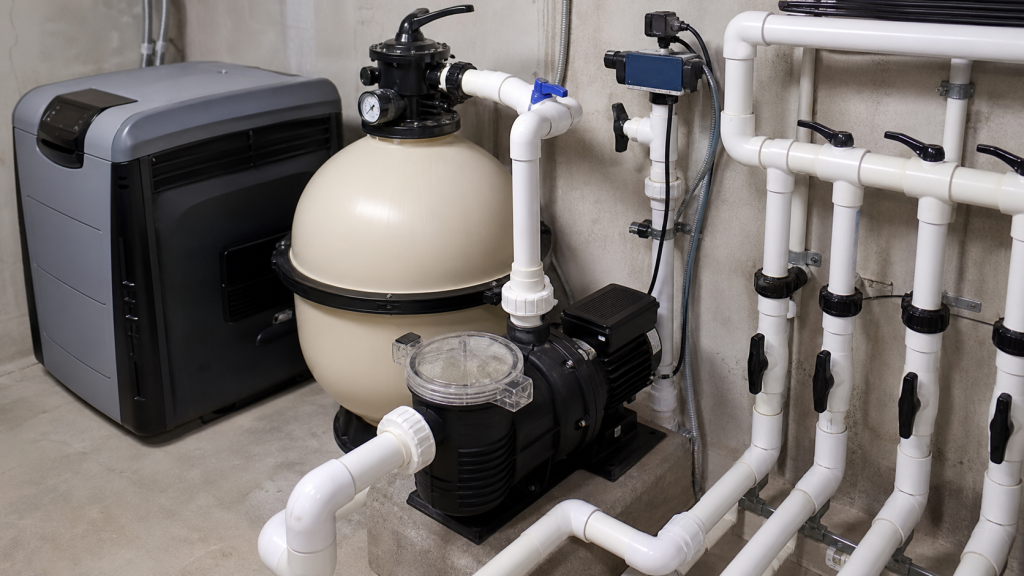
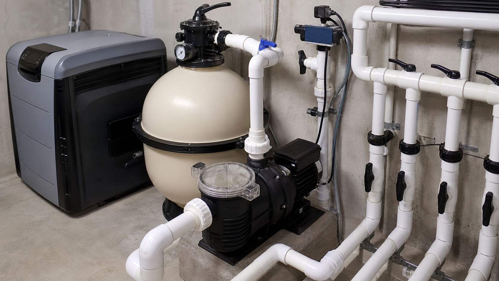
An oversized pool pump increases energy consumption and noise while forcing the filter valve to act as the primary system restriction. Correct pool pump sizing requires matching the pump curve to the system curve at a duty point that delivers required flow against actual total dynamic head. The selection process begins with operating-mode flow requirements, adds measured head losses from piping and equipment, and verifies that the pump operates within its envelope across all conditions.
This article walks through duty-point selection across plumbing, filter, heater, features, speed, and motor parameters. Flow-rate calculation and turnover requirements are covered separately.
الوجبات الرئيسية
- Match the pump curve to system curve at a duty point that meets required flow and head for all operating modes
- Calculate total dynamic head from elevation change, piping friction, and component losses including filter, heater, and fittings
- Select a duty point near best efficiency point (BEP) to minimize energy use and mechanical stress
- Verify that variable-speed operation remains within the pump’s operating envelope at all speeds
- Confirm that NPSHa exceeds NPSHr with margin specified by the pump manufacturer
- Check that motor power rating covers maximum operating power across the speed range
Define the Pool Operating Modes
Pool systems operate in distinct modes with different flow demands. Filtration mode runs continuously or on a schedule to maintain water clarity. Heating mode requires sufficient flow to transfer heat from the heater without triggering low-flow cutouts. Feature modes—waterfalls, jets, spillovers, laminar streams—often demand higher flow than filtration alone. Cleaning mode may use dedicated returns or spa jets at elevated flow rates.
Each mode defines a minimum flow requirement. The pump must deliver that flow against the head present when valves are positioned for that mode. A pool with a spa circuit, deck jets, and a waterfall may have four system curves, each with a different resistance profile.
Record the valve positions and return arrangements for each mode. Note whether features run simultaneously or sequentially. Sequential operation allows the pump to meet peak flow for one mode at a time; simultaneous operation requires the pump to handle combined flow unless dedicated pumps serve individual circuits.
Establish Required Flow for Each Mode
Filtration flow is set by turnover time and local code requirements. Consult the applicable health code or pool standard for minimum turnover rate. For a hypothetical 20,000-gallon residential pool with an eight-hour turnover requirement, the calculation is:
Q = Volume / Time = 20,000 gallons / 8 hours = 2,500 gallons per hour ≈ 42 GPM
Heater flow requirements appear in the heater manufacturer’s specifications. Gas heaters often specify a minimum flow to prevent overheating; heat pumps specify a flow range for optimal heat exchange. Running below the minimum flow causes the heater to cycle on thermal limits; running above the maximum flow reduces heat-transfer efficiency.
Feature flow demands vary widely. Manufacturer specifications for deck jets, waterfalls, laminar jets, vanishing edges, and spa spillovers provide required flow rates. Sum the flows for all features intended to run simultaneously, then add the base filtration flow if features operate during filtration cycles.
Document the required flow for each mode in a table:
Mode | Flow (GPM) | Simultaneous Features |
|---|---|---|
Filtration only | 42 | لا شيء |
Filtration + heating | 45 | Heater minimum per spec |
Filtration + waterfall | 92 | Waterfall per manufacturer |
All features | 120 | Waterfall + deck jets per spec |
The highest flow becomes the design point unless the pump uses variable speed to serve modes independently.
Estimate System Head from the Plumbing Path
Total dynamic head equals the sum of static head, friction head, and component head losses. Static head is the elevation difference between the water surface and the highest discharge point. For a pool at grade discharging to deck-level returns, static head is near zero. For a rooftop pool or elevated spa return, static head equals the vertical rise in feet.
Friction head comes from pipe, fittings, and valves. Use the Darcy-Weisbach equation or friction charts appropriate for the pipe material, diameter, and flow rate. Obtain equivalent length values for fittings from piping handbooks or manufacturer data. Each elbow, tee, valve, and transition adds resistance expressed as equivalent straight pipe length.
Measure or estimate the total equivalent length of suction and discharge piping, including fittings. Calculate friction head using published friction factors or tables for the specific pipe material and size at design flow.
Add static head and friction head to obtain the piping contribution to total dynamic head. This value applies only to the specific flow rate used in the friction calculation. Head loss increases with the square of flow, so doubling the flow quadruples the friction head.
Account for Filter, Heater, Sanitizer, and Fittings
Component head losses dominate residential pool systems. Filter manufacturers publish clean and maximum (terminal) head loss values at rated flow. A clean cartridge or sand filter introduces modest head loss; as the filter loads with debris, head loss climbs to the terminal value that triggers backwash or cleaning. The pump must deliver design flow against maximum filter head, not clean-filter head.
Heater head loss varies by model and heat exchanger design. Consult the heater’s performance data for head loss at design flow. UV sanitizers, ozonators, and chemical feeders add smaller losses that must be included in the total.
Convert all pressure losses to feet of head using:
Head (ft) = Pressure (psi) × 2.31 / Specific Gravity
For fresh water at typical pool temperatures, specific gravity is 1.0, so 1 psi equals 2.31 feet of head.
Sum the component losses in feet and add them to the piping head calculated previously. For a hypothetical system with 6 feet of piping head, 50 feet of filter head at terminal condition, 12 feet of heater head, and 5 feet of accessory head, total dynamic head is 73 feet at design flow.
Select the Duty Point on a Pump Curve
The duty point is the intersection of the system curve and the pump curve. The system curve plots total dynamic head against flow rate, with head rising as flow increases due to friction. The pump curve plots the head the pump can deliver at each flow rate, typically declining as flow increases.
Obtain the certified pump curve from the manufacturer. Residential pool pumps are usually end-suction centrifugal pumps available in single-speed, two-speed, and variable-speed configurations. The curve shows head on the vertical axis and flow on the horizontal axis, often with multiple curves for different impeller diameters or speeds. A properly sized pool pump places the duty point near the best efficiency point to minimize energy use and mechanical stress.
Plot the system curve on the same axes. At zero flow, the system curve starts at static head. At design flow, the curve reaches the calculated total dynamic head. The curve follows the relationship:
H_system = H_static + K × Q²
where H_static is elevation head, K is the system resistance coefficient, and Q is flow rate. Calculate K from the known point:
K = (H_total – H_static) / Q²
For the hypothetical system with 73 feet of head at 50 GPM and 0 feet of static head:
K = 73 / 50² = 0.0292 ft/(GPM)²
The system curve equation becomes:
H_system = 0.0292 × Q²
Identify the pump curve that crosses the system curve near the design flow and head. If the intersection occurs far to the right of BEP, the pump is oversized; it will deliver excess flow, wasting energy and requiring throttling. If the intersection is far to the left of BEP, the pump is undersized and will not meet flow requirements. Consult the pump manufacturer’s data sheet for the acceptable operating range around BEP.
For systems with multiple operating modes, plot each system curve. A filtration-only curve with lower head may cross the pump curve at a different point than the all-features curve. A variable-speed pump can shift between curves by changing speed; a single-speed pump operates where its fixed curve crosses the active system curve.
Choose Variable-Speed Range and Motor Limits
Variable-speed pool pumps use permanent-magnet motors and variable-frequency drives to adjust speed across a range specified by the manufacturer. Flow and head scale with speed according to affinity laws:
Q₂ / Q₁ = N₂ / N₁
H₂ / H₁ = (N₂ / N₁)²
P₂ / P₁ = (N₂ / N₁)³
where Q is flow, H is head, P is power, and N is speed. Reducing speed by half cuts flow in half, reduces head to one quarter, and drops power to one eighth of full-speed values.
Program the pump controller to meet each operating mode’s flow requirement at the lowest practical speed. Filtration mode, with modest flow and head, may operate at reduced speed. Feature modes requiring higher flow run at higher speeds. The controller can schedule speeds by time of day or activate higher speeds based on valve position sensors or feature switches.
Verify that the proposed speed range keeps all operating points within the pump’s operating envelope. Manufacturer data sheets specify minimum and maximum continuous-duty speeds and acceptable operating zones on the pump curve.
Calculate motor power at each operating point using:
Power (HP) = (Q × H × SG) / (3,960 × Efficiency)
where Q is in GPM, H is in feet, SG is specific gravity, and efficiency is a decimal. For the hypothetical duty point at 50 GPM and 73 feet of head with 70% efficiency:
Power = (50 × 73 × 1.0) / (3,960 × 0.70) = 1.32 HP
The motor must provide adequate power at maximum speed and maximum head. Variable-speed motors can modulate torque across the speed range, but total power at any speed must not exceed the motor’s continuous rating.
Verify Suction Velocity, Priming, and Equipment Ratings
Suction-side velocity should remain below the limit specified in the pump installation manual. Calculate velocity from:
Velocity (ft/s) = (Q × 0.408) / (Diameter_inches)²
For 50 GPM in a 2-inch suction line:
Velocity = (50 × 0.408) / 4 = 5.1 ft/s
If velocity exceeds the manufacturer limit, increase pipe diameter.
Check that available net positive suction head (NPSHa) exceeds required NPSH (NPSHr) by the margin specified in the pump curve. NPSHa is the absolute pressure at the pump suction minus the liquid’s vapor pressure, expressed in feet of head:
NPSHa = Atmospheric Pressure + Static Suction Head – Friction Losses – Vapor Pressure
For a pump with suction at pool surface level (zero static head), 3 feet of suction friction loss, atmospheric pressure of 34 feet (sea level), and water vapor pressure of 1 foot at 80°F:
NPSHa = 34 + 0 – 3 – 1 = 30 feet
If the pump curve shows NPSHr of 10 feet at the duty point, verify that the difference meets or exceeds the manufacturer’s recommended margin. Insufficient NPSH causes cavitation, which damages the impeller and reduces performance.
Self-priming pumps require a flooded suction line or an integral priming chamber. Standard centrifugal pumps must be primed manually or by a priming system. Confirm that the pump’s priming capability matches the installation.
Verify that all equipment ratings align. Filter flow rating must meet or exceed design flow. Heater flow range must encompass the operating flow. Valve pressure ratings must exceed maximum system pressure. Piping pressure class should provide margin above operating pressure plus transient pressure events.
Pool Pump Selection Checklist
Use this checklist to confirm that the proposed pump meets system requirements:
- [ ] Required flow for each operating mode documented from turnover requirements, heater specs, and feature manufacturer data
- [ ] Total dynamic head calculated for worst-case condition (maximum filter head, all features active)
- [ ] Duty point plotted on manufacturer pump curve and falls within manufacturer-specified operating range
- [ ] Pump curve intersects system curve at or above required head at design flow
- [ ] Variable-speed operating points remain within pump envelope at all programmed speeds
- [ ] Motor power rating exceeds calculated power at maximum speed and head
- [ ] NPSHa exceeds NPSHr by manufacturer-specified margin at all operating points
- [ ] Suction velocity remains below manufacturer limit at maximum flow
- [ ] Filter, heater, and valve ratings accommodate design flow and pressure
- [ ] Priming method matches installation geometry
- [ ] Pump materials compatible with water chemistry
- [ ] Electrical service provides adequate voltage and phase for motor
- [ ] Installation space permits service access to motor, seal, and impeller
- [ ] Manufacturer curve, motor nameplate data, and installation manual available on site
الأسئلة الشائعة
How does a dirty filter affect pump sizing?
A dirty filter increases system head, shifting the operating point left on the pump curve and reducing flow. Size the pump to deliver design flow at maximum filter head specified by the filter manufacturer. If sized for clean-filter head, the pump will fall short as the filter loads. Monitor pressure rise across the filter; when it reaches the terminal value, backwash or clean the filter to restore design flow.
Can I use a fire or irrigation pump curve for pool sizing?
No. Fire pumps and irrigation pumps serve different duty profiles with different curve shapes, materials, and control requirements. Pool pumps are end-suction centrifugals optimized for moderate flow, moderate head, and continuous or scheduled operation. Use only pumps rated for pool and spa service with curves published for the specific model and impeller.
What happens if I size the pump based on filtration flow alone?
Feature modes and heating may not receive adequate flow. A pump sized for filtration cannot deliver the higher flow required for waterfalls, spa jets, and other features running simultaneously. The result is weak features, heater low-flow faults, or reliance on throttling valves to balance flow between circuits. Size for the highest simultaneous flow demand unless a variable-speed schedule isolates modes.
Does salt content change the pump selection?
Salt increases water density slightly. The effect on head and power is negligible for sizing. The significant factor is corrosion resistance: use pumps with materials compatible with chlorinated saltwater as specified by the manufacturer. Verify that seals, o-rings, and hardware meet the chemical compatibility requirements.
How do I verify the duty point after installation?
Install pressure gauges on the suction and discharge sides of the pump. Measure flow using an inline flow meter or bucket-and-timer method at a return line. Calculate total dynamic head from the gauge readings converted to feet of head. Plot the measured point on the pump curve; it should fall near the design point. If the measured flow is low, check for suction air leaks, clogged impeller, closed valves, or incorrect impeller diameter.
الخاتمة
Correct pool pump sizing matches the pump curve to the system curve at a duty point that meets required flow against actual total dynamic head across all operating modes. Begin with documented flow requirements for filtration, heating, and features from applicable codes and equipment specifications. Calculate total dynamic head from elevation, piping friction, and equipment losses at maximum filter head. Select a pump whose curve intersects the system curve within the manufacturer-specified operating range and verify that variable-speed operation stays within the pump envelope. Confirm that NPSHa exceeds NPSHr per manufacturer requirements, suction velocity remains acceptable, and motor power covers maximum load. Complete the checklist and retain the manufacturer curve, system-head calculation, and valve schedule for commissioning and future reference.