
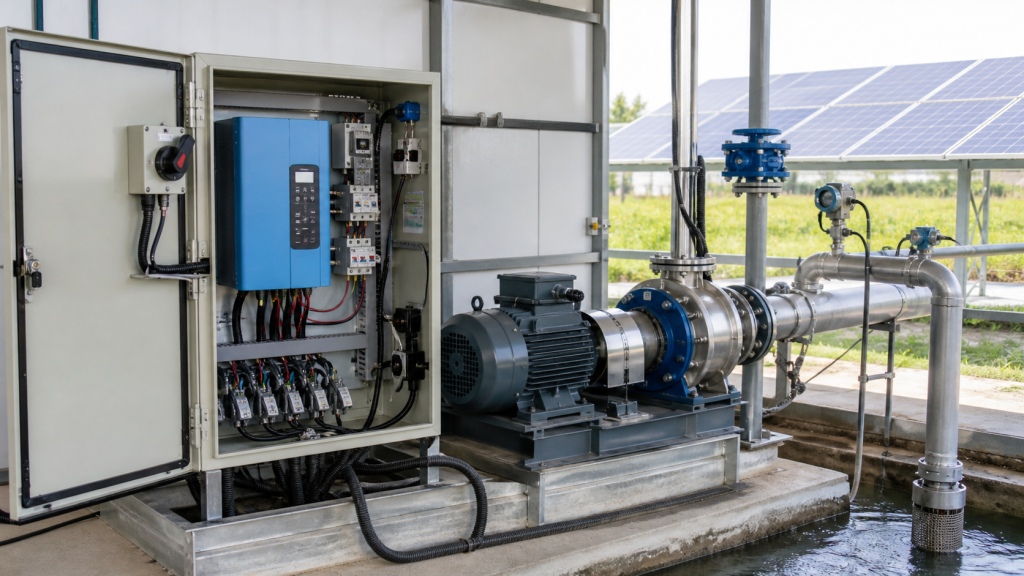
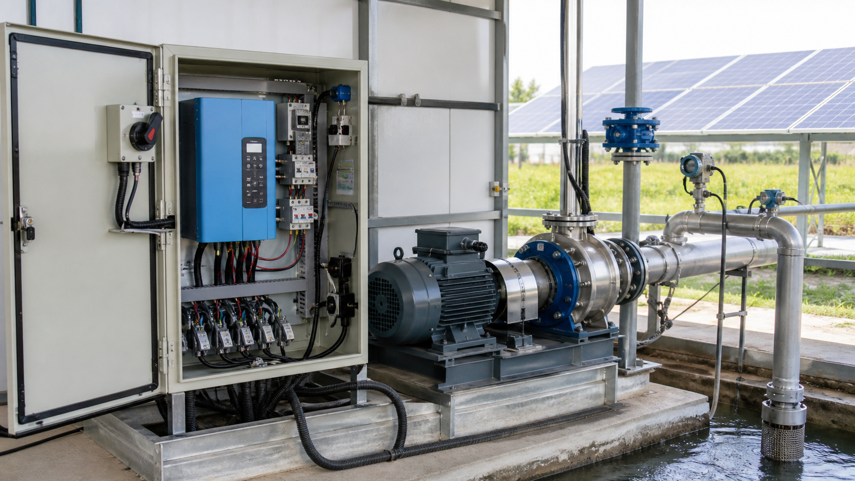
Open the controller cabinet on a solar pumping installation and you see the problem a solar pump controller must solve. Direct current from a photovoltaic array arrives at a voltage and power level that changes every few seconds as clouds pass, sun angle shifts, or cell temperature varies. The three-phase AC motor turning the pump impeller expects stable voltage, controlled frequency, and protection against dry-run, overvoltage, and phase loss. The solar water pump controller sits between them, converting variable DC input into regulated three-phase output while monitoring tank level, suction pressure, and motor current to shut down before damage occurs.
That conversion and protection function explains why solar pump inverter and solar pump controller are used interchangeably in specification documents. Both terms describe the same device: a DC-to-AC inverter with embedded logic that matches photovoltaic supply to motor demand, adjusts speed based on available power, and responds to field sensors that detect dry wells, full tanks, or mechanical faults.
Puntos clave
- A solar pump controller converts variable DC from photovoltaic panels into stable three-phase AC for the pump motor, embedding soft start, speed control, and protection functions in one cabinet.
- The DC input stage must handle the array open-circuit voltage, maximum power current, and voltage fluctuations from shading or temperature swings without tripping on overvoltage or undervoltage.
- Dry-run, tank-level, pressure, and phase-loss inputs prevent motor burnout and bearing damage by stopping the pump before mechanical failure or cavitation occurs.
- Controller selection depends on matching the PV voltage window to the array configuration, motor nameplate data to the output stage, and sensor inputs to the actual field instrumentation.
- Commissioning records that document DC voltage range, motor current at known flow, sensor trigger points, and fault log entries provide the baseline for later troubleshooting.
Where the Controller Sits in a Solar Pump System
The controller occupies the electrical interface between the photovoltaic array and the pump motor. DC cables from the array enter the controller at positive and negative input terminals. Inside, capacitors smooth the ripple and the inverter stage switches that DC into three-phase AC. That AC flows through three output terminals to the motor, and the motor shaft drives the pump.
A second set of wiring terminates at the control board: analog inputs from tank-level floats, pressure transducers, or temperature sensors; digital inputs from dry-run floats or flow switches; and relay outputs that signal alarms or control valves. The controller monitors these inputs in real time and stops the inverter if a fault condition appears.
This architecture contrasts with grid-tied pumping systems that use a standard variable-frequency drive fed by utility power. The solar controller replaces both the grid connection and the VFD, accepting a DC source that cannot supply constant voltage and adapting motor speed to match the power the array delivers at that instant.
DC Input, Inverter Stage, Motor Output, and Control Board
The DC input stage includes a fused disconnect, surge protection, and a capacitor bank. The disconnect allows isolation for maintenance. Surge arrestors clamp voltage spikes from lightning or array switching. Capacitors store energy during each inverter switching cycle and smooth the DC bus voltage seen by the inverter transistors.
Inverter topology in solar pump controllers typically uses insulated-gate bipolar transistors arranged in three half-bridge pairs. Pulse-width modulation controls the transistor gates to synthesize a three-phase AC output at the commanded frequency. Frequency determines motor speed, and speed determines pump flow according to the affinity laws. By varying the PWM pattern, the controller adjusts motor speed to track the maximum power the array can deliver under current irradiance.
The motor output stage includes current sensors in each phase and a contactor or solid-state relay that opens the motor circuit if a fault is detected. Current sensors feed the control board, which calculates motor load and compares it against the configured trip threshold.
The control board runs firmware that executes the soft-start ramp, speed-control algorithm, and protection logic. It reads DC bus voltage, motor current, and external sensor inputs every few milliseconds and updates the PWM commands sent to the inverter gates. This closed-loop control maintains stable motor operation even as the PV array output varies throughout the day.
Soft Start, Speed Control, and Motor Compatibility
Soft start limits inrush current by ramping motor frequency from zero to the target speed over several seconds. A three-phase induction motor can draw several times its nameplate current during direct-on-line starting. That surge stresses the inverter transistors, heats motor windings, and can cause voltage sag that trips the controller on undervoltage. A controlled ramp reduces starting current and prevents nuisance trips during morning startup.
Speed control adjusts motor frequency in response to DC bus voltage. When irradiance is high and the array delivers full power, the controller runs the motor at maximum frequency—typically 50 or 60 Hz depending on motor design. As irradiance falls, DC bus voltage drops and the controller reduces frequency proportionally. This algorithm ensures the motor load never exceeds the power the array can supply, avoiding brownout and shutdown.
Motor compatibility depends on matching the controller output voltage and current ratings to the motor nameplate. A 380 V three-phase motor requires a controller rated for at least 380 V line-to-line output. The controller current rating must equal or exceed motor full-load current. Undersizing the controller causes overcurrent trips; oversizing increases cost without improving performance.
Permanent-magnet motors and induction motors both work with solar pump controllers, but their control characteristics differ. Permanent-magnet motors deliver higher efficiency at partial load and can start under high static head without stalling. Induction motors cost less and tolerate brief overloads better. Controller firmware must be configured for the installed motor type to ensure correct torque response and field-weakening behavior above base speed.
Dry-Run, Tank-Level, Pressure, and Fault Inputs
Dry-run protection stops the motor when the pump loses suction, preventing bearing seizure and mechanical seal failure. A float switch mounted in the well or suction tank closes when water level drops below the minimum safe level. The controller reads this normally open contact and shuts down if the contact opens. Some controllers add a time delay to avoid tripping on transient level fluctuations caused by wave action or inflow surges.
Tank-level inputs control upper and lower storage thresholds. When the storage tank reaches the high-level setpoint, a float switch signals the controller to stop pumping. When the tank drains to the low-level setpoint, pumping resumes. This start-stop logic prevents overflow and maintains a usable reserve without requiring a pressure tank or manual intervention.
Pressure transducers provide analog 4–20 mA or 0–10 V signals proportional to discharge pressure. The controller compares this feedback against a configured pressure setpoint and adjusts speed to maintain constant pressure as demand varies. Pressure control is useful in domestic water supply and irrigation laterals where downstream flow changes throughout the day.
Phase-loss and overcurrent faults are detected internally by the control board. If one motor phase opens due to a loose connection or blown fuse, the controller trips on phase imbalance. If motor current exceeds the configured limit for more than the programmed time delay, the controller trips on overcurrent. Both conditions indicate a wiring fault, mechanical overload, or bearing failure that requires immediate investigation before damage spreads.
Select by PV Voltage Window, Motor Data, and Pump Duty
Controller selection starts with the photovoltaic array configuration. Count the number of panels in series and multiply the panel open-circuit voltage by that number to find the array open-circuit voltage. The controller maximum input voltage must exceed this value. Then multiply the panel maximum power voltage by the number of series panels to find the nominal operating voltage. The controller input range must include this operating voltage with margin for temperature and irradiance variation.
For example, a 12-panel series string using panels rated 48 V open-circuit and 40 V at maximum power produces 576 V open-circuit and 480 V operating. The controller must be rated for at least 600 V input and have a minimum operating voltage below 480 V to avoid shutdown during partial shading.
Next, match motor nameplate data. Record motor rated voltage, full-load current, frequency, and power factor. The controller output voltage must equal motor rated voltage. Controller output current must equal or exceed motor full-load current with margin for inrush and momentary overload. Motor frequency—50 or 60 Hz—determines the controller frequency setting and the pump speed at which the manufacturer curve applies.
Pump duty point establishes the power requirement. From the system head calculation, find the total dynamic head and flow rate the pump must deliver. Read motor input power at that duty point from the pump performance curve. Verify that the photovoltaic array can supply this power at the design irradiance. If the array is undersized, the controller will reduce motor speed and the pump will operate below its best efficiency point.
Sensor compatibility matters as much as power ratings. Confirm that the controller terminal strip accepts the voltage and signal type each field device provides. A controller configured for dry contact inputs cannot read a 4–20 mA pressure signal without an external signal converter.
Basic Wiring Interfaces and Commissioning Checks
DC input wiring uses cable rated for the maximum array current and outdoor UV exposure. Positive and negative cables from the array terminate at the controller DC input terminals. Polarity must be correct; reversing DC polarity damages the input stage. After terminating the cables, measure open-circuit voltage at the controller input with a multimeter before closing the DC disconnect. Confirm that the measured voltage falls within the controller rated input range.
Motor output wiring uses three-conductor cable rated for the motor full-load current. U, V, and W terminals on the controller connect to the motor phase leads. Phase rotation determines motor direction. For centrifugal pumps, direction must match the rotation arrow cast into the pump casing. Incorrect rotation reduces flow and can damage the impeller. After wiring, perform a direction check by running the motor at low speed and verifying water discharge before increasing to full speed.
Sensor wiring runs from field devices to the controller terminal strip. Float switches use two-wire connections to normally open or normally closed contacts. Pressure transducers use shielded three- or four-wire cable for power supply and signal return. Label each sensor at both the field device and the controller terminal to match the commissioning drawing. A mislabeled dry-run float will shut down the system when the tank is full rather than when the well is dry, creating a diagnostic puzzle that wastes site visits.
Commissioning sequence follows this order: verify DC voltage and polarity, check motor phase rotation, test each sensor input by manually operating the float or applying a simulated signal, run the pump at low speed and confirm water flow, ramp to full speed and record motor current, and log initial fault history. Document these measurements in a commissioning record attached to the controller cabinet door. Future troubleshooting depends on comparing current readings against the baseline established during commissioning.
Read Fault History before Replacing Hardware
Solar pump controllers log fault events with a timestamp, fault code, and the operating condition at the time of the trip. This history remains in nonvolatile memory even after power loss. Before replacing a suspected failed controller, connect to the diagnostic port and download the fault log. A pattern of overvoltage faults at midday suggests undersized surge protection or a failing capacitor. Repeated dry-run trips at sunrise indicate the well recharge rate cannot support the pump flow rate, not a controller defect.
Fault codes follow a numeric or alphanumeric scheme defined in the controller manual. Common codes include:
- E01 or OV: DC overvoltage, array voltage exceeded input limit
- E02 or UV: DC undervoltage, insufficient irradiance to sustain minimum speed
- E03 or OC: motor overcurrent, load exceeded rated current
- E04 or PH: phase loss, one motor phase open or imbalanced
- E05 or DR: dry-run, suction level sensor opened
Inspect the operating data logged with each fault. If an overcurrent fault occurred at 95 A motor current but the motor nameplate shows 80 A full-load current, the trip was correct and the cause is mechanical overload or bearing friction, not a false alarm. Conversely, an overcurrent trip at 65 A with an 80 A motor indicates the current sensor has drifted out of calibration or the trip threshold was misconfigured.
Clearing the fault log after downloading preserves memory space and establishes a clean baseline for post-repair monitoring. If the same fault reappears within hours of a controller replacement, the root cause lies in the external wiring, motor, pump, or installation, not the controller hardware.
Controller Specification Checklist
Use this checklist to collect the data needed to specify a solar pump controller for a project or to verify an existing controller matches the installed equipment:
Parámetro | Required Value | Source Document |
|---|---|---|
PV array open-circuit voltage | \_\_\_\_ V DC | Panel datasheet × number of series panels |
PV array maximum power voltage | \_\_\_\_ V DC | Panel datasheet × number of series panels |
PV array short-circuit current | \_\_\_\_ A DC | Panel datasheet × number of parallel strings |
Motor rated voltage | \_\_\_\_ V AC | Motor nameplate |
Motor full-load current | \_\_\_\_ A AC | Motor nameplate |
Motor rated frequency | 50 / 60 Hz | Motor nameplate |
Motor type | Induction / PM | Motor nameplate or manufacturer data |
Pump rated power | \_\_\_\_ kW | Pump performance curve |
Sensor inputs required | Dry-run / Tank level / Pressure | System drawing |
Protection class | IP54 / IP65 / NEMA 4 | Installation environment |
Ambient temperature range | \_\_\_\_ to \_\_\_\_ °C | Site weather data |
Complete this table during the design phase and attach it to the controller purchase order. A controller that meets every line of this specification will integrate with the system without field modifications.
Preguntas frecuentes
Can a solar pump controller work with a single-phase motor?
Solar pump controllers typically output three-phase AC and require a three-phase motor. Single-phase AC output requires a different inverter topology and is uncommon in solar pumping above 1 kW. If the existing motor is single-phase, replace it with a three-phase motor matched to the controller output voltage and frequency, or specify a single-phase solar controller from the manufacturer.
What happens when a cloud passes over the array during pumping?
The controller reduces motor speed as DC bus voltage drops, maintaining operation at reduced flow rather than shutting down. When irradiance returns, speed ramps back up. Frequent speed changes throughout the day are normal and do not harm the motor or pump. However, if the system trips on undervoltage during every cloud, the array is undersized or the minimum operating voltage is configured too high.
Do solar pump controllers include maximum power point tracking?
Some models integrate MPPT algorithms that adjust DC bus voltage to extract maximum power from the array at each irradiance level. Others operate at a fixed voltage and rely on array sizing to keep the operating point near maximum power. Controllers with MPPT cost more but can deliver higher daily pumped volume in variable weather. For mission-critical water supply, MPPT may justify the cost; for non-critical irrigation, fixed-voltage control may be sufficient.
Why does the motor hum but not turn when starting in the morning?
Insufficient torque at low irradiance prevents the motor from breaking static friction or overcoming high starting head. This condition is common with induction motors starting against closed check valves. Solutions include increasing the array size to provide more starting power, installing a permanent-magnet motor with higher starting torque, or adding a bypass valve that opens during startup to reduce head until the motor reaches operating speed.
How long should a solar pump controller last before replacement?
Electrolytic capacitors in the DC bus are typically the life-limiting component. In hot climates where cabinet temperature exceeds the manufacturer’s rated ambient limit, expect shorter service life. In moderate climates with good ventilation, longer operation is achievable. Firmware updates and fan replacements extend life, but capacitor aging eventually causes voltage ripple that trips the controller on DC bus faults. Consult manufacturer documentation for specific component ratings and expected service intervals.
Conclusión
A solar pump controller specification depends on accurate data from the PV array voltage window, motor nameplate, and pump operating duty. Gather these values, complete the specification checklist, and confirm that sensor inputs match the field instrumentation before issuing a purchase order. After installation, document the commissioning measurements—DC voltage, motor current, sensor trigger points, and initial fault log—in a record that stays with the cabinet. That baseline allows you to distinguish controller defects from system problems when a fault occurs, and fault history narrows the troubleshooting path before hardware is replaced.