
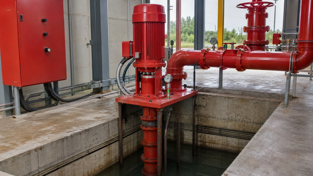
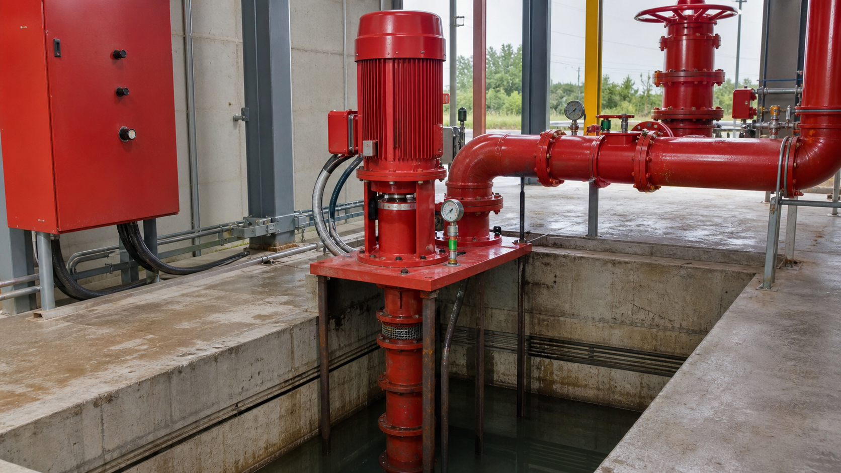
A vertical turbine fire pump sits above a water source that cannot be lifted economically or reliably by suction alone. The pump extends downward into a well, wet pit, or reservoir, positioning one or more impeller stages below the minimum water level so that positive pressure always reaches the first stage. This arrangement solves the suction-lift problem but trades conventional pump-room access for a submerged bowl assembly, a column pipe that carries both water and the drive shaft, and a discharge head mounted at floor level.
Before specifying a vertical turbine fire pump, confirm that the available water level makes suction-lift geometry impossible or unreliable, that the well or pit diameter accommodates the bowl outside diameter plus installation clearance, and that the fire-protection design authority will accept a listed vertical turbine assembly in place of a horizontal configuration.
Puntos clave
- A vertical turbine fire pump is required when the water surface sits too far below the pump-room floor for a conventional suction line to maintain positive NPSHa at rated flow.
- The bowl assembly contains one or more impeller stages; the column pipe supports the assembly and encloses the line shaft that transmits torque from the surface-mounted driver.
- Minimum submergence must prevent vortex formation and air entrainment at the intake, specified by the manufacturer as a function of intake diameter and approach velocity.
- Right-angle gear drives or vertical hollow-shaft motors couple to the top of the discharge head; the entire driveline from motor shaft to bowl impellers must be aligned within manufacturer tolerances before acceptance testing.
- Certified fire-pump curves include churn, rated, and overload test points; each test must be witnessed and recorded to satisfy listing requirements and the authority having jurisdiction.
- Long-term reliability depends on periodic pull-and-inspect cycles to measure wear-ring clearance, bearing condition, and shaft straightness—a task that requires lifting equipment and planned downtime.
When Fire-Water Supply Calls for a Vertical Turbine Arrangement
Fire-protection systems demand continuous water availability at the specified pressure and flow. When the water source is a municipal main under adequate pressure, a horizontal split-case or end-suction pump mounted in a room at grade can draw from the incoming service line. When the source is a ground-level storage tank, suction piping drops to the tank connection and atmospheric pressure on the tank surface provides the necessary NPSHa.
A vertical turbine fire pump becomes necessary when the water surface lies below the elevation where atmospheric pressure alone can lift the column of water to the pump inlet. Practical suction lift for centrifugal pumps has physical limits governed by atmospheric pressure, vapor pressure, and friction loss; in fire-water service, where reliability cannot tolerate priming failures or cavitation at rated flow, even modest lift becomes problematic. Wells, deep reservoirs, and below-grade storage tanks routinely present static lifts that make suction-lift geometry unworkable.
The vertical turbine configuration moves the impeller stages down into the water. The bowl assembly submerges below the minimum expected water level, so that hydrostatic pressure at the bowl inlet always exceeds vapor pressure by the required NPSH margin. Discharge rises through the column pipe to a discharge head at floor or grade level, where it connects to the system piping.
This architecture is common in municipal water supply, agricultural irrigation, and industrial process applications. Fire-protection use introduces two additional constraints: the pump and driver must carry a recognized listing, and the installed assembly must meet the installation standard enforced by the authority having jurisdiction.
Bowl Assembly, Column, Line Shaft, and Discharge Head
The bowl assembly contains the impeller or impellers, diffuser or volute passages, and the bearings that support the lower end of the rotating assembly. Single-stage bowls use one impeller; multi-stage designs stack two or more stages in series to reach higher total head. Each stage adds its own head contribution; the discharge from one stage enters the suction of the next through an interstage passage cast into the bowl housing.
The impeller diameter, number of stages, and specific speed determine the pump curve. A given flow and head requirement can be met with different stage configurations. Fire-pump curves are certified by testing the specific bowl configuration at the specified speed. Changing the impeller diameter or adding a stage alters the curve and invalidates the certification.
The column pipe extends from the top of the bowl assembly to the discharge head. It carries the discharge flow and encloses the line shaft. Column sections are supplied in lengths that vary by manufacturer and coupled with threaded or flanged joints. Setting depth determines the number of sections required. The column inside diameter must be large enough to keep friction loss acceptably low; excessive column friction reduces the net discharge head available to the system.
The line shaft transmits torque from the driver down to the impeller. Shaft sections couple with keyed sleeves or threaded connections, and bearings inside the column support the shaft at intervals specified by the manufacturer. Two bearing arrangements are common: oil-lubricated bearings housed in retainer assemblies inside the column, or water-lubricated bearings where discharge water flows through the shaft tube and lubricates the bearings directly. Oil-lubricated designs require periodic inspection and oil replacement; water-lubricated designs depend on clean water and continuous flow to prevent bearing wear.
The discharge head bolts to the top of the column and provides the connection point for the system discharge piping. It also carries the stuffing box or mechanical seal that prevents water from leaking around the shaft where it exits the pressure boundary. The driver couples to the top of the shaft through a rigid or flexible coupling; in right-angle gear drives, the motor mounts horizontally and a gearbox transmits torque to the vertical shaft.
Minimum Water Level, Submergence, and Intake Quality
The bowl inlet must remain submerged at all times. Submergence is the vertical distance from the water surface to the centerline of the bowl inlet. Insufficient submergence allows air to enter the intake through vortex formation or surface drawdown, introducing gas into the impeller and causing loss of prime, surging flow, vibration, and potential mechanical damage.
Minimum required submergence depends on intake diameter, approach velocity, and the geometry of the intake structure. Manufacturer recommendations account for these variables; fire-pump applications often specify more conservative margins to ensure reliability during long-duration operation. If the water source is subject to seasonal variation, the pump setting depth and intake design must accommodate the lowest expected water level with adequate submergence margin.
Intake screens or trash racks prevent debris from entering the bowl. Screen open area must be large enough that approach velocity through the screen remains low to avoid excessive head loss and debris accumulation. In wells, the screen or casing perforations serve as the intake boundary; in open reservoirs, a separate intake structure surrounds the bowl assembly and directs flow toward the inlet while keeping floating debris and sediment away from the suction.
Water quality affects bearing life and wear-ring clearance. Suspended sand or grit accelerates wear on impeller shrouds, diffuser vanes, and bearings. Water-lubricated bearing designs are especially sensitive; particles larger than the bearing clearance can jam the bearing or score the shaft sleeve. Wells drawing from sandy aquifers may require a finer intake screen or settling basin ahead of the fire-pump intake. If water quality data shows high suspended solids, specifying oil-lubricated bearings or mechanical seals with external flush may be necessary.
Driver, Right-Angle Gear, and Controller Interfaces
Fire-pump drivers are limited to electric motors and diesel engines under most listing standards. Electric motor drives use constant-speed induction motors rated for continuous duty at the pump’s rated power plus a margin. The motor mounts either directly above the discharge head on a vertical hollow shaft or horizontally on a right-angle gear drive. Vertical hollow-shaft motors eliminate the need for a coupling and gearbox, simplifying the driveline and reducing maintenance, but they require custom motor designs and may not be available in all frame sizes.
Right-angle gear drives couple a standard horizontal motor to the vertical pump shaft through a gearbox. The motor mounts on a baseplate alongside the discharge head, and a horizontal drive shaft connects the motor to the gearbox input. This arrangement accommodates any standard motor and makes motor replacement straightforward, but it introduces additional rotating components, bearings, and lubrication points. Gear efficiency varies by design; the power loss appears as heat in the gearbox oil and must be accounted for in the motor selection.
Diesel engine drives use direct-coupled or gear-reduced configurations. Direct coupling requires matching the engine speed to the pump speed, which may limit engine selection. Gear reduction allows the engine to run at its optimal speed while the pump operates at the speed required by the certified curve. Diesel-driven fire pumps must include starting batteries, fuel supply, cooling system, exhaust, and control panel—all integrated into a listed package.
The controller starts and stops the pump in response to system pressure, monitors operating conditions, and provides alarms. Electric fire-pump controllers are listed assemblies that include overload protection sized not to trip during overload testing, isolation for sequential starting of multiple pumps, and interlocks to prevent simultaneous operation of maintenance bypass valves. Diesel controllers manage cranking attempts, monitor engine parameters, and include automatic transfer logic if the electric driver fails.
Installation Alignment and Column Support
Alignment begins at the foundation. The discharge head must sit on a level, grouted baseplate or structural support with sufficient rigidity to prevent settlement or deflection under operating loads. The column hangs from the discharge head, and any misalignment at the top translates to lateral load on the bowl bearings and shaft whip during operation.
After the discharge head is secured, column sections are assembled one at a time. Each section is lowered into the well or pit, aligned with the section below, and coupled. Line shaft sections are inserted as the column builds, with each shaft segment coupled to the one below. Bearing retainers or shaft sleeves are installed at the manufacturer-specified intervals to support the shaft and limit deflection.
The final column section supports the bowl assembly. The bowl is lowered to the setting depth, and the column is adjusted so that the impeller position matches the design clearance between the impeller shrouds and the diffuser or bowl casing. This clearance is specified by the manufacturer and is critical to hydraulic performance; excessive clearance reduces efficiency and head, while insufficient clearance risks impeller rub during thermal expansion or bearing wear.
Once the bowl is positioned, the discharge head is bolted to the column top, and the driver or right-angle gear is mounted. Shaft alignment between the driver and the pump shaft is checked using dial indicators, laser alignment tools, or feeler gauges depending on the coupling type. Misalignment introduces cyclic loads that accelerate bearing wear, shaft fatigue, and seal leakage. Total indicated runout at the coupling should fall within the manufacturer’s tolerance.
Lateral support may be required if the column length exceeds the critical buckling length or if lateral forces from piping, seismic loads, or wind are significant. Support guides at intermediate depths prevent lateral deflection without restraining axial movement due to thermal expansion. In deep wells, the weight of the column and shaft assembly itself can produce significant axial loads; the discharge head or a separate thrust bearing must carry the suspended weight plus the hydraulic thrust generated during operation.
Churn, Rated, and Overload Test Points on the Certified Curve
A certified fire-pump curve includes three test points: churn (shutoff), rated, and overload. The overload flow is typically a percentage above rated flow specified by the applicable listing standard. Each point is witnessed during factory acceptance testing or field commissioning, and the measured head and power must fall within the tolerance bands defined by the listing standard.
Churn occurs when the discharge valve is fully closed and flow is zero. At churn, the pump develops maximum head and minimum power. Churn pressure must not exceed the rating of the discharge piping, fittings, or system components. If the system is rated for a specific pressure, the pump churn pressure plus the static suction pressure must remain below that limit.
Rated flow and head define the pump’s design duty point. The rated point is selected to match the system demand calculated from the hydraulic analysis of the fire-protection network. At rated flow, the pump must deliver at least the rated head, and the power draw must not exceed the motor nameplate rating.
The overload point tests the pump’s ability to deliver increased flow when system demand exceeds the design case—for example, if additional sprinkler heads open or hose streams are added. At the overload flow, total head drops according to the pump curve, but the pump must continue to operate without cavitation, excessive vibration, or mechanical distress. Power draw at overload is the maximum expected load on the driver; the motor must be sized to handle this power continuously.
If measured values at any test point fall outside the certified tolerance, the pump does not meet its listing and cannot be placed in service. Common causes include incorrect impeller diameter, wrong shaft speed, excessive wear-ring clearance, or air entrainment at the intake. Field testing uses calibrated flow meters, pressure gauges, and power analyzers; instrument accuracy must meet the requirements of the listing standard.
Inspection Access and Long-Term Reliability
Vertical turbine fire pumps operate submerged, so visual inspection of the bowl, impeller, bearings, and shaft requires pulling the assembly from the well or pit. This is a planned maintenance task requiring lifting equipment—a crane, hoist, or derrick capable of handling the combined weight of the column, shaft, and bowl assembly. For deep settings, the weight can be substantial, and disassembly must proceed in reverse order: unbolt the driver, disconnect the coupling, remove the discharge head, and lift the column in sections while simultaneously withdrawing the line shaft.
Inspection intervals depend on water quality, operating hours, and observed performance trends. A pump that shows declining discharge pressure, increasing vibration, or rising power draw may require inspection before the scheduled interval.
During inspection, measure wear-ring clearance with feeler gauges or inside micrometers. Clearance growth beyond the manufacturer’s limit reduces head and efficiency; replacing wear rings or impeller shrouds restores performance. Inspect bearings for wear, scoring, or discoloration. Oil-lubricated bearings should show even contact patterns and no galling; water-lubricated bearings should show no erosion or embedding of abrasive particles. Check shaft straightness with dial indicators or a straight edge; bent shafts indicate misalignment, bearing failure, or impact damage.
Seals and O-rings should be replaced during each disassembly, and threaded connections should be cleaned and re-lubricated with anti-seize compound. Record all measurements in a maintenance log to track wear trends and predict the next intervention. If multiple pumps serve the same system, stagger inspection schedules so that at least one pump remains in service at all times.
Project Data Required for Listed-System Coordination
Specifying a vertical turbine fire pump requires coordination among the system designer, pump supplier, and installing contractor. The system designer provides the hydraulic requirement: rated flow, total head, and the available water level under minimum and maximum conditions. The designer must also identify the listing standard, the authority having jurisdiction, and any local amendments to the installation code.
The pump supplier confirms that a listed assembly exists to meet the requirement and provides the certified curve, driver selection, column length, bowl diameter, and setting depth. The supplier should also specify minimum submergence, required well or pit diameter, recommended intake screen area, and alignment tolerances. If a right-angle gear drive is required, the supplier provides the gearbox type, ratio, and lubrication requirements.
The installing contractor verifies site conditions: well diameter and depth, structural support for the discharge head, clearances for column installation and future removal, electrical service capacity for the motor or space for the diesel engine package, and rigging access for lifting. The contractor is responsible for foundation preparation, column alignment, driver mounting, piping connections, and coordination of the acceptance test.
A complete submittal package for review by the authority having jurisdiction should include:
- Certified pump curve showing churn, rated, and overload test points with tolerances
- Driver nameplate data and control schematic
- Column assembly drawing showing shaft length, bearing spacing, and setting depth
- Installation drawing showing foundation plan, piping layout, and clearances
- Hydraulic calculation supporting the selection of rated flow and head
- Listing certificates for the pump, driver, and controller
- Operation and maintenance manual with torque specifications, lubrication schedule, and inspection procedures
The acceptance test is the final gate. Flow, pressure, and power are measured at churn, rated, and overload points, and the results are compared to the certified curve. If the pump meets its rating, the test report is signed by the installing contractor, the authority having jurisdiction, and the owner’s representative, and the system is placed in service. If it does not, investigate the root cause—incorrect impeller, wrong speed, air entrainment, or instrument error—before repeating the test.
Preguntas frecuentes
Can a vertical turbine fire pump operate if the water level drops below the design minimum?
Operating with insufficient submergence allows air to enter the bowl, causing surging flow, loss of prime, and potential shaft or bearing damage. If the water source is subject to seasonal drawdown, the setting depth must be specified for the lowest expected level with adequate margin. If the level drops unexpectedly, shut down the pump and investigate before resuming operation.
How does column friction loss affect the rated head?
The total head developed by the bowl assembly is the sum of the head from each stage. Column friction reduces the net head available at the discharge flange. The certified curve accounts for column friction at the tested column length. If the field installation uses a longer column, additional friction loss may require a larger column diameter or adjustment to the number of stages to maintain rated discharge head.
What causes shaft whip in vertical turbine fire pumps?
Shaft whip is cyclic lateral deflection of the line shaft, typically resulting from misalignment between the driver and the pump shaft, insufficient bearing support at intermediate depths, or unbalanced impellers. Whip induces vibration, accelerates bearing wear, and can lead to shaft fatigue failure. Realign the driver coupling and verify that bearing spacing matches the manufacturer’s recommendations.
Is field testing required after pulling and reinstalling the bowl assembly?
Yes. Disassembly and reassembly can alter impeller clearances, bearing alignment, or shaft runout. After reinstallation, run the pump at rated flow and measure head, power, and vibration. Compare the results to the original acceptance test data. If performance has degraded, adjust impeller clearance, realign the shaft, or inspect for wear before placing the pump back in service.
Can a vertical turbine fire pump run continuously at churn?
Running at churn generates heat in the pump casing due to recirculation and friction. Without flow through the discharge, this heat is not removed, and the water temperature inside the pump rises. Prolonged churn operation can cause flashing, thermal expansion that closes wear-ring clearances, and damage to seals or bearings. Install a recirculation line sized to remove at least the churn power input if extended churn operation is anticipated.
Conclusión
A vertical turbine fire pump moves the hydraulic lifting problem below grade, placing the impeller assembly where positive pressure is always available. Before committing to this configuration, confirm the minimum water level under all operating conditions, verify that a listed assembly meets the required flow and head, secure acceptance from the authority having jurisdiction, and plan for the lifting and disassembly cycles that inspection and long-term reliability demand. The acceptance test and certified pump curve remain the final proof that the installed system matches the design requirement.