
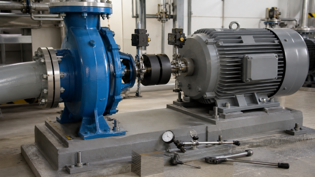
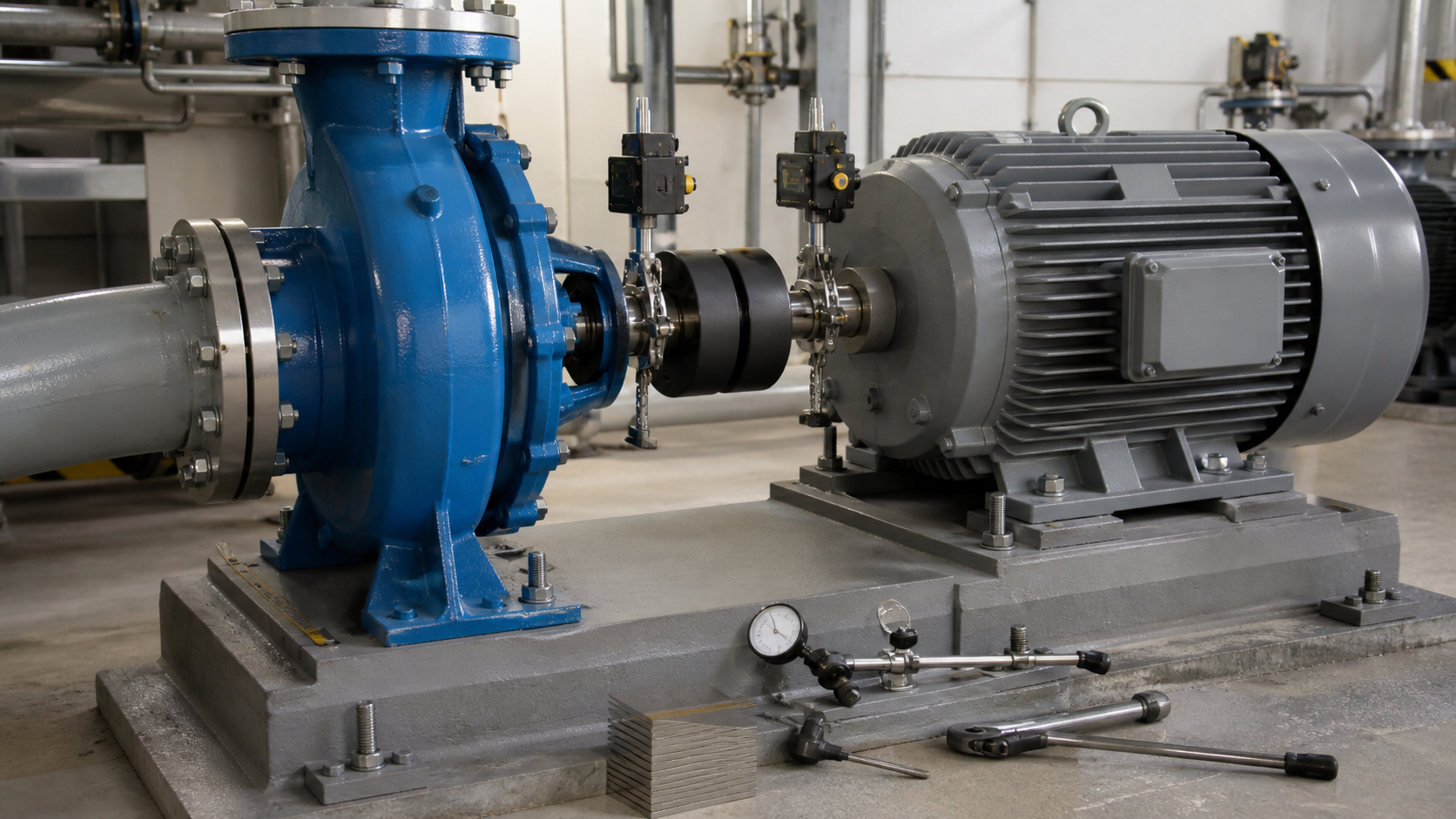
Pump motor alignment is the process of positioning the motor and driven pump shafts so their centerlines are collinear within specified tolerances. You begin after the pump and motor have been set on the baseplate but before piping, wiring, or guard installation. The goal is to prevent premature bearing failure, seal leakage, coupling wear, excessive vibration, and shaft fatigue by ensuring the rotating elements share a common axis under all operating conditions—cold, hot, pressurized, and under full load.
The field procedure follows a fixed sequence: lockout and coupling removal, baseplate and foundation inspection, soft-foot correction, rough alignment, laser alignment measurement and correction, piping connection, thermal stabilization recheck, coupling assembly, and final documentation. Skipping soft-foot correction or failing to recheck alignment after pipe stress or thermal growth invalidates the work.
Belangrijkste opmerkingen
- Correct soft foot before any alignment measurement; a single loose or uneven mounting foot distorts the machine frame and produces false readings.
- Laser alignment targets two points on both shafts with real-time readings, yielding angular and parallel offset values that replace the trial-and-error of dial indicators.
- Rough alignment brings the shafts close enough to assemble the coupling before connecting piping; piping stress and thermal growth will shift the final position.
- Recheck alignment after piping is connected and after the first thermal cycle; discharge pipe weight, thermal expansion, and foundation movement all affect shaft position.
- Document the as-left vertical and horizontal offset at the coupling face, shim stack under each motor foot, and manufacturer’s target values for future maintenance.
Define the Alignment Target and Machine Train
Alignment tolerances depend on shaft speed, coupling type, bearing design, and the manufacturer’s installation drawing. Consult the pump and motor installation manuals for specific limits. Frame-mounted pumps with flexible couplings typically allow larger offsets than close-coupled pumps with rigid couplings. High-speed machines require tighter tolerances than low-speed units.
The machine train consists of the driver (electric motor or engine), coupling, and driven equipment (pump). The driver is normally the movable element; the pump remains fixed to its foundation and connected to piping. Shim stacks under the motor feet raise or lower the motor shaft to match the pump shaft elevation. Horizontal movement is achieved by loosening the motor anchor bolts and shifting the motor frame on the baseplate.
Thermal growth complicates the target. Cast iron pump casings expand when handling hot liquids, shifting the pump shaft upward and outward. The target cold alignment must compensate for this movement. If the pump manufacturer specifies a hot offset target, set the motor shaft position accordingly when cold so the shafts align at operating temperature. Without a thermal target from the manufacturer, plan to measure hot alignment during commissioning and adjust the cold shim stack if necessary.
Lockout, Coupling, Baseplate, and Foundation Checks
Begin with lockout and tagout of the motor electrical supply. Verify zero voltage at the motor terminal box with a calibrated meter. Lock the breaker and tag the control panel to prevent accidental startup during alignment work.
Remove the coupling guard and inspect the coupling halves. Flexible couplings use elastomer spiders, jaw elements, or grid springs that accommodate small misalignment; rigid couplings do not. Record the coupling type and part number. If the coupling is worn, cracked, or hardened, replace it before alignment.
Inspect the baseplate for cracks, corrosion, loose grouting, and standing water. Tap the grout with a hammer; a hollow sound indicates a void under the baseplate. Voids allow the baseplate to flex under load, shifting alignment. If voids are present, re-grout the baseplate before proceeding. The foundation bolts must be tight and free of corrosion.
Check the baseplate for flatness by placing a precision straight edge across the motor and pump mounting pads. Gaps indicate baseplate distortion or uneven grouting. Distortion transfers directly to the machine frames and cannot be corrected by shimming alone. A twisted baseplate requires re-grouting or replacement.
Find and Correct Soft Foot
Soft foot is the condition where one or more mounting feet do not make full contact with the baseplate when all hold-down bolts are loose, or where tightening a single bolt lifts another foot. Soft foot distorts the motor frame, bending the shaft and producing a false alignment reading. Misalignment from soft foot causes premature bearing failures, seal leakage, and excessive vibration even when the measured alignment appears correct.
To check for soft foot, loosen all motor hold-down bolts. Place a feeler gauge or dial indicator under each foot. Tighten one bolt at a time to the specified torque and measure the gap change at the other three feet. If tightening a single bolt lifts another foot, soft foot is present.
There are four types of soft foot:
- Parallel soft foot: One foot is higher than the others. Correct by adding shims under the low foot until all feet contact the baseplate simultaneously when bolts are loose.
- Angular soft foot: A foot is tilted, contacting at one edge. Correct by adding a tapered shim or machining the foot flat.
- Induced soft foot: The foot is flat when bolts are loose, but tightening a bolt on the opposite side of the frame lifts the foot. Caused by baseplate distortion or frame warping. Correct by shimming to relieve the induced stress or re-machining the baseplate.
- Sprung soft foot: The motor frame twists when bolts are tightened, lifting a diagonal foot. Caused by excessive piping stress or a twisted baseplate. Correct the root cause rather than adding shims.
Recheck soft foot after each shim change. Once all bolts can be tightened without lifting any foot beyond the manufacturer’s specified limit, soft foot is corrected. Record the final shim stack thickness under each foot before proceeding to alignment.
Rough Alignment before Connecting Piping
Rough alignment brings the motor and pump shafts close enough that the coupling can be assembled without forcing. Use a precision straight edge across the coupling halves or dial indicators mounted on one shaft reading against the other. Target values depend on the coupling manufacturer’s requirements.
For vertical adjustment, add or remove shims under all four motor feet equally. Measure the gap between coupling faces at top, bottom, and both sides with feeler gauges. Adjust shims until the gaps are reasonably equal.
For horizontal adjustment, loosen the motor hold-down bolts and shift the motor frame sideways. Tap the motor with a soft hammer or use jack bolts if the motor has them. Measure the side gaps with feeler gauges. Shift the motor until side gaps are approximately equal. Tighten the hold-down bolts and recheck; tightening may shift the motor slightly.
Do not connect piping until rough alignment is complete. Piping stress forces the shafts out of alignment. If you align the shafts with piping already connected, you are aligning to the piped condition rather than the free-shaft condition. When the piping is later modified or replaced, alignment will be lost.
Laser Alignment Measurement and Correction Sequence
Laser alignment systems measure angular and parallel misalignment in real time by mounting laser emitters and detectors on the coupling hubs and rotating the shafts together. Laser alignment is considered the most precise and fastest technique for shaft alignment, replacing dial indicator methods that required multiple rotation and measurement cycles.
The laser system reports four offset values:
- Vertical parallel offset: The vertical distance between shaft centerlines at the coupling face.
- Vertical angular offset: The vertical angle between shaft centerlines, reported as an angular gap or as the projected offset at a specified distance from the coupling face.
- Horizontal parallel offset: The horizontal distance between shaft centerlines at the coupling face.
- Horizontal angular offset: The horizontal angle between shaft centerlines.
The system also calculates the shim thickness required under each motor foot to bring the shafts into alignment, eliminating trial-and-error shimming.
Mount the laser emitter on the pump coupling hub and the detector array on the motor coupling hub according to the system manufacturer’s instructions. Zero the system with the shafts in a reference position, then rotate both shafts together through the required arc. The system averages multiple measurement points to cancel runout and sag. The tolerance zone is displayed graphically; accept only readings within the specified tolerance band.
If the motor shaft is low and offset, the display shows the correction needed. Add shims equally under all four motor feet to raise the shaft, and shift the motor frame to correct horizontal offset. The system updates the offset values in real time as you make corrections.
Tighten all hold-down bolts to the specified torque after each shim change. Recheck alignment; tightening often shifts the motor slightly. Continue adjusting shims and horizontal position until both vertical and horizontal offsets fall within the tolerance zone specified by the pump or coupling manufacturer.
Recheck after Pipe Connection and Thermal Stabilization
Connect the suction and discharge piping after achieving acceptable alignment with the shafts free. Use pipe supports and flexible connectors to minimize piping stress on the pump nozzles. Piping should be self-supporting; hanging discharge pipe weight on the pump casing will pull the pump shaft downward and out of alignment with the motor.
After piping is connected, recheck alignment with the laser system. If vertical or horizontal offset has increased beyond tolerance, piping stress is the cause. Adjust pipe supports or install expansion joints to relieve the stress. Do not re-shim the motor to compensate for piping stress; the stress will vary with pressure and temperature, and the shaft alignment will shift with operating conditions.
Start the pump and allow it to reach normal operating temperature. Shut down and immediately recheck alignment while the pump is still hot. If the pump manufacturer provided a hot-alignment target, compare the measured offsets to the target. If no target was provided, record the hot offset as the new baseline. If the hot offset exceeds the acceptable tolerance, adjust the cold shim stack to bring the hot alignment within range. Allow the pump to cool and verify that cold alignment remains acceptable.
Thermal growth is most significant on pumps handling liquids above ambient temperature or when the motor is mounted on a separate foundation with different thermal expansion characteristics. Checking hot alignment once during commissioning eliminates uncertainty.
Coupling, Lubrication, Guard, and Rotation Checks
Assemble the coupling according to the manufacturer’s instructions. Flexible couplings have specific torque requirements for the spider or grid retention bolts; rigid couplings require precise gap settings between coupling halves. Do not force the coupling together if the gap is uneven; an uneven gap indicates residual misalignment or a bent shaft.
Lubricate the coupling if it is a grease-lubricated design. Use the lubricant type and volume specified by the coupling manufacturer. Over-greasing can fling lubricant onto the motor windings or pump seals; under-greasing causes premature wear.
Install the coupling guard and verify that it does not contact the coupling, shafts, or motor frame during rotation. A loose guard can vibrate against the coupling and produce noise that mimics bearing failure.
Before starting the pump under power, verify rotation direction by bumping the motor starter. If the pump rotates backward, interchange any two motor leads at the terminal box. Backward rotation produces no discharge pressure and can damage some impeller and seal designs.
Check that all anchor bolts are tightened to the specified torque, the coupling guard is secure, and the pump casing is vented or primed as required. Verify that suction and discharge valves are positioned correctly and that the system is ready to accept flow.
Record the Final As-Left Condition
Document the final alignment offsets, shim stack thickness under each motor foot, piping configuration, operating temperature, and any deviations from the manufacturer’s recommended alignment procedure. This record becomes the baseline for future maintenance and troubleshooting.
Typical as-left alignment record:
Parameter | Value |
|---|---|
Vertical offset (cold) | As measured |
Horizontal offset (cold) | As measured |
Vertical offset (hot) | As measured |
Horizontal offset (hot) | As measured |
Front left motor foot shim | Total mm/in |
Front right motor foot shim | Total mm/in |
Rear left motor foot shim | Total mm/in |
Rear right motor foot shim | Total mm/in |
Coupling type | Mfr and size |
Laser system model | Model used |
Technician | Naam |
Date | Date completed |
Photograph the shim stack and the laser alignment display screen. If the motor must be removed for repair or replacement, the photographs provide a starting point for realignment rather than beginning from zero.
Attach the alignment record to the pump maintenance history file. Include the installation drawing, motor nameplate data, coupling part number, and a copy of the manufacturer’s alignment procedure. Future technicians will need this information to determine whether vibration or seal leakage is caused by alignment drift or by another failure mode.
Schedule a realignment check after the initial run-in period and at regular intervals thereafter. Foundation settlement, piping modifications, and motor repairs can shift alignment outside tolerance. Catching alignment drift early prevents bearing and seal damage that would otherwise require a pump rebuild.
FAQs
What causes alignment to drift after the pump has been running for several months?
Foundation settlement, piping thermal cycling, and repeated start-stop cycles gradually shift the motor and pump relative to each other. Grouted baseplates settle as the grout cures and compresses under load. Discharge piping that heats and cools daily expands and contracts, pulling the pump casing in different directions. Repeated motor starts generate torque that can loosen hold-down bolts or shift the motor frame if bolts were not properly torqued. Recheck alignment periodically to catch drift before it causes bearing or seal failure.
Can I skip laser alignment and use dial indicators or straight edges instead?
Dial indicators measure runout and sag in addition to misalignment, requiring you to rotate the shafts, plot the readings, and calculate the true offset mathematically. The process takes longer and introduces more measurement error than laser alignment. Straight edges provide only a rough estimate of parallel offset and cannot measure angular offset. For critical pumps or high-speed applications, laser alignment provides accurate results that dial indicators cannot match consistently. Use laser alignment unless the pump is a low-speed, non-critical unit where rough alignment meets the application requirements.
How do I know if piping stress is causing misalignment rather than a motor mounting problem?
Measure alignment with the piping disconnected. If the alignment falls within tolerance with the pipes off but goes out of tolerance when the pipes are reconnected, piping stress is the cause. Adjust pipe supports, install expansion loops, or add flexible connectors to relieve the stress. If alignment is out of tolerance even with the piping disconnected, the motor mounting, soft foot, or baseplate is the problem. Do not attempt to shim the motor to compensate for piping stress; the stress varies with pressure and temperature, and the alignment will shift unpredictably during operation.
What is the difference between angular and parallel misalignment, and which is more damaging?
Parallel misalignment means the shaft centerlines are parallel but offset vertically or horizontally. Angular misalignment means the centerlines intersect at an angle, producing a V-shaped gap at the coupling faces. Both types damage bearings and couplings, but angular misalignment concentrates the bending load near the coupling and generally produces more rapid wear. Laser alignment systems report both types separately. Correct parallel offset by shimming the motor equally; correct angular offset by shimming two feet on the same side of the motor (front or rear) without changing the opposite side. Most misalignment problems combine both types and require multiple correction cycles.
Should I realign the pump after replacing the motor or repairing the pump?
Yes. Motor frame dimensions vary between manufacturers and production runs. Installing a replacement motor requires complete realignment starting from soft-foot correction. Pump repairs that involve disassembling the casing, replacing the impeller, or machining wear rings can shift the pump shaft relative to the mounting feet. After any pump or motor work, treat the machine as a new installation and follow the full alignment procedure including thermal recheck. Assuming that alignment is still correct after a repair or replacement leads to premature bearing and seal failure.
Conclusie
Pump motor alignment prevents bearing, seal, and coupling failures by ensuring the motor and pump shafts rotate around a common centerline under all operating conditions. The field procedure begins with soft-foot correction, proceeds through rough and laser alignment with free shafts, confirms that piping stress has not shifted alignment, and rechecks after thermal stabilization. Document the final shim stack, cold and hot offset values, and coupling configuration so future technicians can verify alignment or restore it after maintenance. Start your next alignment project by verifying that the manufacturer’s installation drawing specifies the cold and hot alignment targets, and confirm that your laser alignment system is calibrated to the pump and coupling manufacturer’s requirements.