
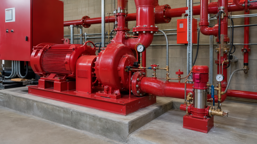
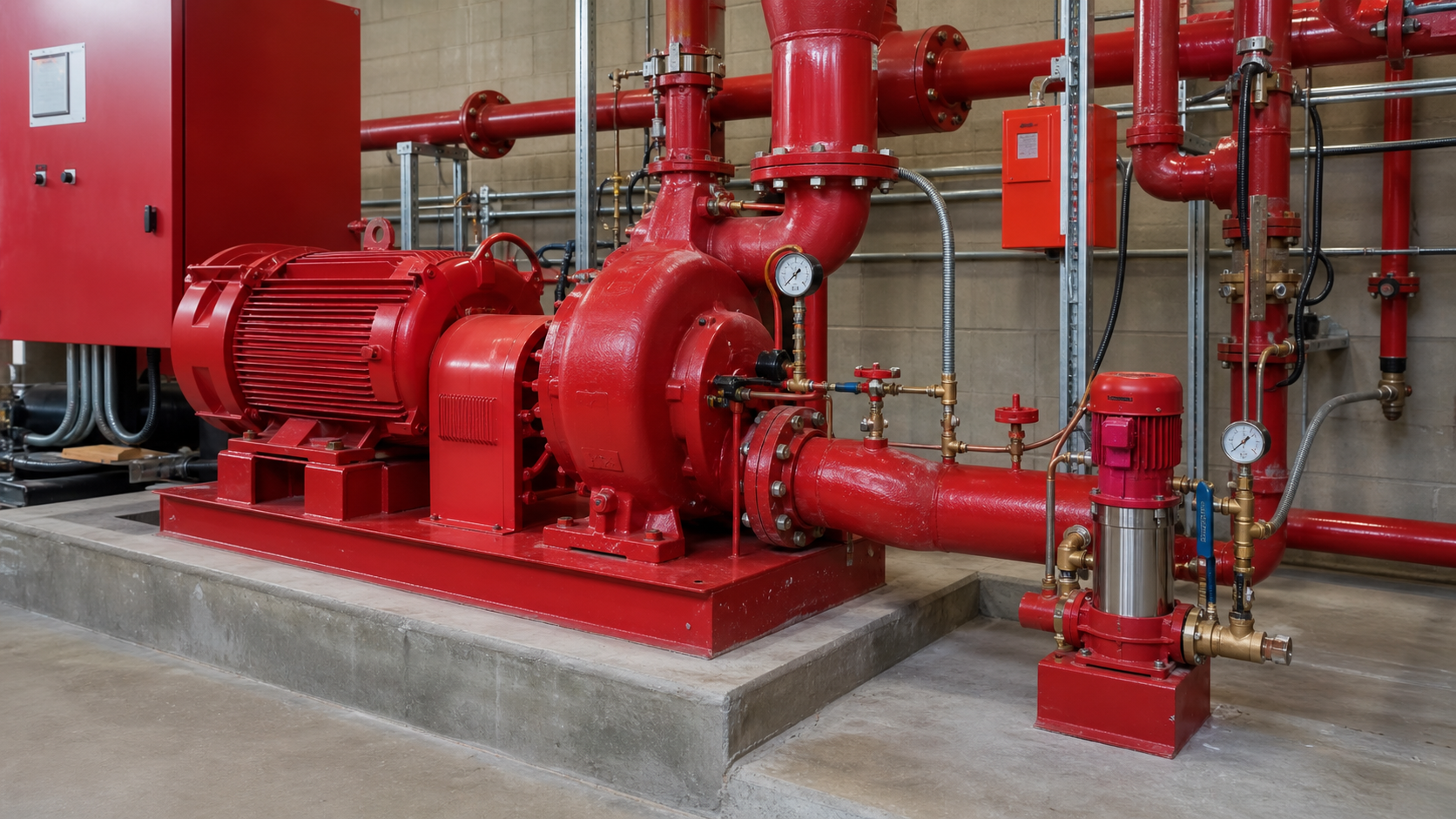
A fire protection system loses 2 psi over 24 hours from valve-seat leakage and thermal expansion. Which pump should respond—the jockey pump or the main fire pump?
The jockey pump handles this task. The jockey pump vs fire pump decision separates pressure maintenance from emergency fire flow. The jockey pump is a small-capacity unit that compensates for normal system leakage and prevents the fire pump from false starts. The fire pump is a large-capacity, NFPA 20-certified machine that delivers rated flow when sprinklers open or hose valves operate. Each has distinct capacity, pressure settings, control logic, and testing requirements. Confusing their roles, oversizing the jockey pump, or setting pressures incorrectly creates nuisance alarms, missed fire events, or equipment damage.
This guide compares function, staging logic, capacity boundaries, driver choices, testing methods, and control conflicts so plant engineers, contractors, and maintenance teams can verify that each pump performs its intended role.
Основные выводы
- The jockey pump maintains system pressure against minor leakage and operates intermittently on pressure switches; the fire pump delivers rated fire flow and starts only when pressure drops below the fire-pump cut-in setting.
- Jockey pump pressure must exceed fire pump start pressure—a minimum of 10 psi per NFPA guidance—to prevent false fire-pump starts, and jockey pump capacity must be small enough that a sprinkler opening or hose discharge immediately triggers the fire pump.
- Controllers stage the two pumps through separate pressure switches: jockey on/off at higher pressures, fire pump start at lower pressure, ensuring each pump responds to its intended demand without interference.
- Driver and relief arrangements differ: jockey pumps use standard motors without mandatory backup, while fire pumps require listed drivers and certified relief valves for churn protection per NFPA 20.
- Testing each pump independently—jockey pump with drain valves, fire pump with flow meters—verifies performance without one pump masking the other’s failure or degraded capacity.
Jockey Pumps Maintain Pressure; Fire Pumps Deliver Fire Flow
The jockey pump compensates for slow pressure loss in a standpipe, sprinkler, or hydrant system. Valve-stem leakage, packing drips, thermal contraction, and air dissolution cause system pressure to sag even when no water flows out. A jockey pump restores pressure before the main fire pump sees the drop. The pump runs intermittently—starting when pressure falls to its cut-in setting, stopping when pressure reaches cut-out—and may cycle several times per hour or per day depending on system tightness.
The fire pump delivers rated flow to open sprinklers or hose streams. When a sprinkler head fuses or a fire hose opens, system pressure collapses faster than the jockey pump can recover. The fire pump controller senses the low-pressure condition and starts the main pump, which supplies the design flow at the required pressure. Fire pumps are listed under NFPA 20 and carry certified performance curves; jockey pumps are not fire pumps under the standard and do not require NFPA 20 listing.
Confusing the two leads to undersized fire pumps or oversized jockey pumps that delay the fire pump’s start or mask sprinkler activation.
Capacity and Pressure Roles Are Not Interchangeable
Jockey pump capacity must be small enough that a single sprinkler opening overwhelms the jockey pump and triggers the fire pump. Design practice sizes jockey pump flow based on measured or estimated system leakage rate, but never so large that it can supply even a fraction of fire demand. As a sizing reference, a fire pump rated for hundreds of gallons per minute might pair with a jockey pump handling several gallons per minute. If the jockey pump were sized to deliver significant flow, it could partially supply a few open sprinklers and delay the fire pump’s start, allowing pressure to drop before the main pump engages.
Jockey pump pressure must exceed fire pump cut-in pressure by a margin so that normal jockey cycling does not cross the fire pump’s start threshold. If the fire pump starts at 95 psi and the jockey pump cuts out at 100 psi, any momentary sag during jockey restart could false-start the fire pump. NFPA guidance recommends that jockey pump pressure exceed fire pump start pressure by at least 10 psi. For example, an operator might set jockey pump cut-in at 105 psi, cut-out at 110 psi, and fire pump cut-in at 95 psi. The exact margin depends on system characteristics, piping configuration, and pressure-switch accuracy. This arrangement ensures the jockey pump handles leakage without starting the fire pump, and the fire pump starts immediately when real demand appears.
Fire pump shutoff head defines the upper limit of system pressure when no flow occurs. The jockey pump must develop enough head to reach its cut-out setpoint under these conditions, meaning jockey pump shutoff head should exceed fire pump shutoff head. Otherwise, when the fire pump completes a test or false start and shuts down, the jockey pump cannot restore the system to normal standby pressure. The specific head increase required depends on suction conditions and system pressure losses.
How Controllers Stage the Two Pumps
A pressure maintenance pump vs fire pump controller uses separate pressure switches to stage the two machines. The jockey pump controller monitors system pressure through a sensing line tapped into the discharge header, upstream of any isolation valves. When pressure falls below the jockey cut-in setpoint, the controller closes a relay, starting the jockey pump motor. The pump runs until pressure rises to the cut-out setpoint, then stops. This cycle repeats as leakage drains pressure back down.
The fire pump controller also monitors system pressure but at a lower threshold. If pressure continues to fall—because a sprinkler opens or the jockey pump fails—and drops below the fire pump cut-in setpoint, the fire pump controller starts the main pump. The fire pump runs continuously until manually stopped or until pressure rises above its cut-out setpoint. Many fire pump controllers disable automatic cut-out or set it well above normal operating pressure to prevent nuisance stops during fire events.
Staging logic ensures that:
- Minor leakage triggers only the jockey pump.
- Major demand (sprinkler activation) immediately triggers the fire pump.
- Jockey pump failure (unable to maintain pressure) eventually triggers the fire pump, providing a backup alarm path.
Pressure switch calibration and sensing-line placement are critical. If the sensing line taps downstream of a closed valve, both pumps see atmospheric pressure and fail to start. If switches are set too close together, jockey cycling false-starts the fire pump. Periodic testing verifies switch setpoints against a calibrated gauge.
Normal Leakage, Test Demand, and Actual Fire Demand
Three operating states define the jockey pump vs fire pump interaction:
Normal leakage state: System pressure sags slowly from valve drips and thermal effects. The jockey pump cycles periodically, restoring pressure in small increments. Fire pump remains off. This is the intended steady-state condition.
Test demand state: During churn tests or flow tests, operators open drain valves or flow meters to simulate fire demand. The fire pump starts and delivers rated flow while the jockey pump may continue to run (if not manually isolated) but contributes negligible flow. Controllers and flow instruments verify that each pump meets its certified performance curve. After the test, the fire pump is manually stopped, and the jockey pump restores system pressure.
Actual fire demand state: A sprinkler opens or hose valve opens, dropping pressure faster than the jockey pump can respond. System pressure falls through the jockey cut-in, then immediately through the fire pump cut-in. The fire pump starts and supplies full rated flow. The jockey pump may remain running but is hydraulically irrelevant—its small output is lost in the fire pump’s flow. The fire pump continues to run until the incident is resolved and the system is manually reset.
Understanding these states clarifies why jockey pump capacity must stay small. If the jockey pump could supply significant flow, it might stabilize pressure during a partial sprinkler activation, delaying the fire pump’s start and leaving insufficient flow for additional heads to operate.
Driver, Suction, Discharge, and Relief Arrangements
Drivers: Jockey pumps use standard electric motors, single-phase or three-phase, without mandatory redundant power or backup drivers. Because jockey pump failure does not immediately jeopardize life safety—the fire pump will eventually start as pressure decays—NFPA 20 does not mandate dual drivers for jockey pumps. Fire pumps, in contrast, require a listed electric motor with reliable power or a diesel engine. Many jurisdictions require one electric and one diesel pump in parallel for redundancy. Fire pump motor controllers carry additional certifications and interlocks.
Suction and discharge: Both pumps draw from the same suction source (municipal main, storage tank, or reservoir) and discharge into the same system header. The jockey pump discharge typically taps into the fire pump discharge downstream of the fire pump’s check valve and isolation valve. This arrangement allows the jockey pump to pressurize the system independently when the fire pump is off. A check valve on the jockey pump discharge prevents backflow from the system when the jockey pump stops. Some designs place the jockey pump suction upstream of the fire pump to avoid interference; others share a common suction header. Consult the system’s hydraulic drawing to verify valve sequencing.
Relief valves: Fire pumps require a listed circulation relief valve to protect the pump from overheating during churn (no-flow) conditions and to limit discharge pressure. The relief valve opens at a setpoint above the fire pump’s rated shutoff head, diverting a small flow back to the suction source or a drain. Jockey pumps may or may not have dedicated relief valves, depending on design. Because jockey pumps run against closed valves regularly, an oversized jockey pump without relief can overpressurize the system and damage gaskets, gauges, or pipe joints.
Testing Each Pump without Masking a Fault
Independent testing verifies that each pump performs its role and that one pump’s operation does not hide the other’s failure.
Jockey pump test: Close the fire pump discharge valve (or confirm fire pump is off and disabled). Open a small drain valve or inspector’s test connection, allowing flow. Observe that system pressure falls to the jockey pump cut-in setpoint, the jockey pump starts, and pressure recovers to the cut-out setpoint. Measure jockey pump discharge pressure with a calibrated gauge. Record start/stop pressures and cycle time. If the jockey pump cannot restore pressure or cycles continuously without reaching cut-out, the pump may be undersized, worn, or the system leakage exceeds design assumptions.
Fire pump test: Isolate or disable the jockey pump so it cannot interfere. Open the fire pump’s flow test connection or main drain valve to a flow meter. Start the fire pump manually or by dropping system pressure below the controller’s cut-in setpoint. Measure discharge pressure and flow at specified test points per the certified pump curve. Confirm that measured head matches the curve within acceptable tolerance for listed pumps. Verify that the relief valve opens at the correct pressure during churn. Record suction pressure, discharge pressure, flow, motor amps, and any abnormal vibration or noise. After the test, close the test valve, stop the fire pump, and re-enable the jockey pump. The jockey pump should restore system pressure to standby within minutes.
Annual full-flow test: NFPA 25 requires periodic flow testing of fire pumps. During this test, the jockey pump is often left running but contributes negligible flow compared to the fire pump’s output. After the fire pump test, confirm that the jockey pump restores system pressure. If the jockey pump fails during the year, periodic churn tests of the fire pump may not detect the jockey fault, so regular jockey pump cycling checks are prudent.
Common Misapplications and Control Conflicts
Oversized jockey pump: A large-capacity jockey pump on a fire system can supply partial sprinkler flow, delaying fire pump start. The correct jockey flow is sized for leakage makeup, not fire demand.
Insufficient pressure margin: Setting the jockey cut-out close to the fire pump cut-in leaves minimal buffer. Pressure transients during jockey pump start or stop can false-start the fire pump. Maintain adequate separation based on system behavior and code requirements.
Jockey pump running continuously: If the jockey pump never reaches its cut-out pressure, system leakage may exceed jockey capacity, the cut-out switch has failed, or the jockey pump has lost performance. Identify and repair leaks first; if leaks are repaired and the pump still runs continuously, test the jockey pump curve and verify switch settings. Continuous operation overheats the motor and wears the seal.
Fire pump starting without sprinkler flow: If the fire pump starts during normal jockey cycling, the jockey cut-in setpoint may be too close to the fire pump cut-in, or the fire pump pressure switch has drifted. Recalibrate switches and increase the margin. Alternatively, the jockey pump may have failed entirely, allowing pressure to decay past the fire pump threshold.
Jockey pump discharge piping undersized: A small jockey pump on undersized piping may experience excessive friction loss, preventing the pump from reaching cut-out pressure. Size jockey pump piping for low velocity to minimize head loss.
Relief valve set incorrectly: If the jockey pump relief valve opens during normal operation, the pump cannot build enough pressure to reach cut-out. Relief should open above the highest intended operating pressure but below the system’s maximum allowable working pressure.
Sensing line obstructed or mislocated: A plugged sensing line reads atmospheric pressure, preventing both pumps from starting. An open sensing line downstream of a closed valve shows zero pressure, false-starting both pumps. Verify sensing line taps into the system header upstream of all isolation valves and install blow-down valves or sediment traps to prevent blockage.
Comparison Table for Design Review
Параметр | Jockey Pump | Пожарный насос |
|---|---|---|
Функция | Maintain system pressure, compensate leakage | Deliver rated fire flow to sprinklers or hoses |
Flow capacity | Small (sized for leakage makeup) | Large (per system hydraulic calculation) |
Pressure setpoint | Cut-in and cut-out above fire pump start | Cut-in below jockey cut-in; cut-out often disabled |
Driver | Standard electric motor, no backup required | Listed electric motor or diesel, often dual drivers |
Сертификация по стандарту NFPA 20 | Not required | Required for fire service pumps |
Control logic | Automatic start/stop on pressure switch | Automatic start on low pressure, manual stop |
Run cycle | Intermittent (cycles per hour or day) | Continuous during fire event until manual reset |
Relief valve | Optional or small-capacity drain | Listed circulation relief, opens at churn pressure |
Testing frequency | Periodic cycling check recommended | Per NFPA 25 requirements |
Последствия сбоя | Pressure decays; fire pump eventually starts | Insufficient fire flow; life-safety risk |
Use this table during design reviews, commissioning walkthroughs, and maintenance planning to confirm that each pump’s capacity, pressure, driver, and control settings align with its role.
Вопросы и ответы
Can the jockey pump supply fire flow if the fire pump fails?
No. The jockey pump is intentionally sized for small leakage makeup flow, far below the minimum fire flow required by hydraulic calculation. Attempting to use the jockey pump for fire suppression leaves the system dangerously undersupplied. If the fire pump fails, the jockey pump will run continuously but cannot restore pressure once sprinklers open. Install redundant fire pumps rather than relying on the jockey pump for emergency flow.
What happens if both pumps start simultaneously?
If both pumps run, the fire pump dominates the hydraulic system due to its far greater capacity. The jockey pump contributes negligible flow and may experience high discharge pressure if it is a positive-displacement design. For centrifugal jockey pumps, the pump simply rides back on its curve toward shutoff head. No immediate damage occurs, but the jockey pump wastes energy. Proper pressure-switch staging should prevent simultaneous starts except during commissioning or testing. If both start routinely, check switch calibration and pressure margins.
How do you size jockey pump head when fire pump shutoff head varies with suction pressure?
Jockey pump head must be set relative to system pressure, not absolute discharge pressure. If the fire pump draws from a variable-level tank, its discharge pressure at shutoff varies with suction pressure. Calculate fire pump shutoff head at minimum suction condition (lowest tank level), add appropriate margin, and set the jockey pump cut-out pressure to that value. Then calculate the jockey pump’s required head as cut-out pressure minus minimum suction pressure. Verify that the selected jockey pump can develop this head at its rated flow. Some designs use a pressure-reducing valve downstream of the jockey pump to decouple jockey and fire pump head variations.
Should the jockey pump be isolated during fire pump flow tests?
It depends on test objectives. For fire pump certification tests, the jockey pump is typically left in service to prove that the system operates as designed—jockey pump running has negligible effect on fire pump flow measurements because of the capacity difference. For diagnostic tests where you suspect jockey pump interference or want to isolate fire pump performance, close the jockey pump discharge valve and disable its controller. After the test, re-open the jockey pump isolation valve and confirm that the jockey pump restores system pressure.
Can a variable-speed drive replace the jockey pump’s pressure switch?
Yes. A VFD-controlled jockey pump can modulate speed to maintain constant system pressure, eliminating pressure cycling and reducing motor starts. The VFD receives a signal from a pressure transducer and adjusts pump speed to match leakage flow. This approach reduces mechanical wear and provides smoother pressure control. However, the jockey pump must still be sized for low capacity to avoid masking fire demand, and the fire pump controller must retain an independent low-pressure switch to start the fire pump if the VFD-controlled jockey pump cannot maintain setpoint. VFD cost and complexity are justified when cycling rates or pressure stability requirements warrant the investment.
Заключение
The jockey pump maintains standby pressure against minor leakage, while the fire pump delivers rated flow during fire events. Proper sizing, pressure staging, independent testing, and control logic ensure that each pump performs its role without interference. Before commissioning or troubleshooting a fire protection system, verify jockey pump cut-out pressure, fire pump cut-in pressure, measured system leakage, and switch calibration against a certified gauge, then document these setpoints in the system’s operation and maintenance manual.