
title: "MPPT Solar Pump Controllers: How They Work and How to Match Them"
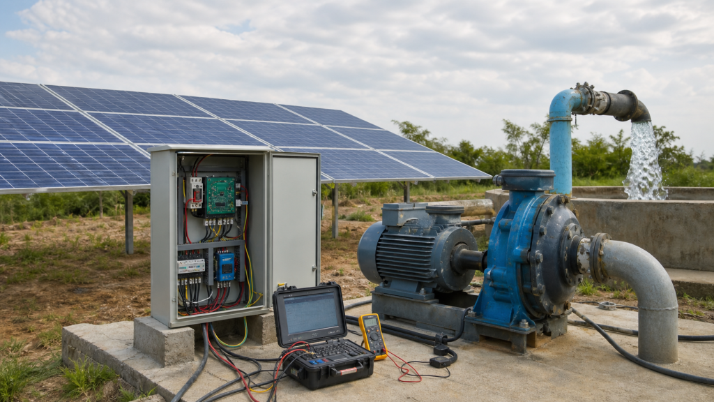
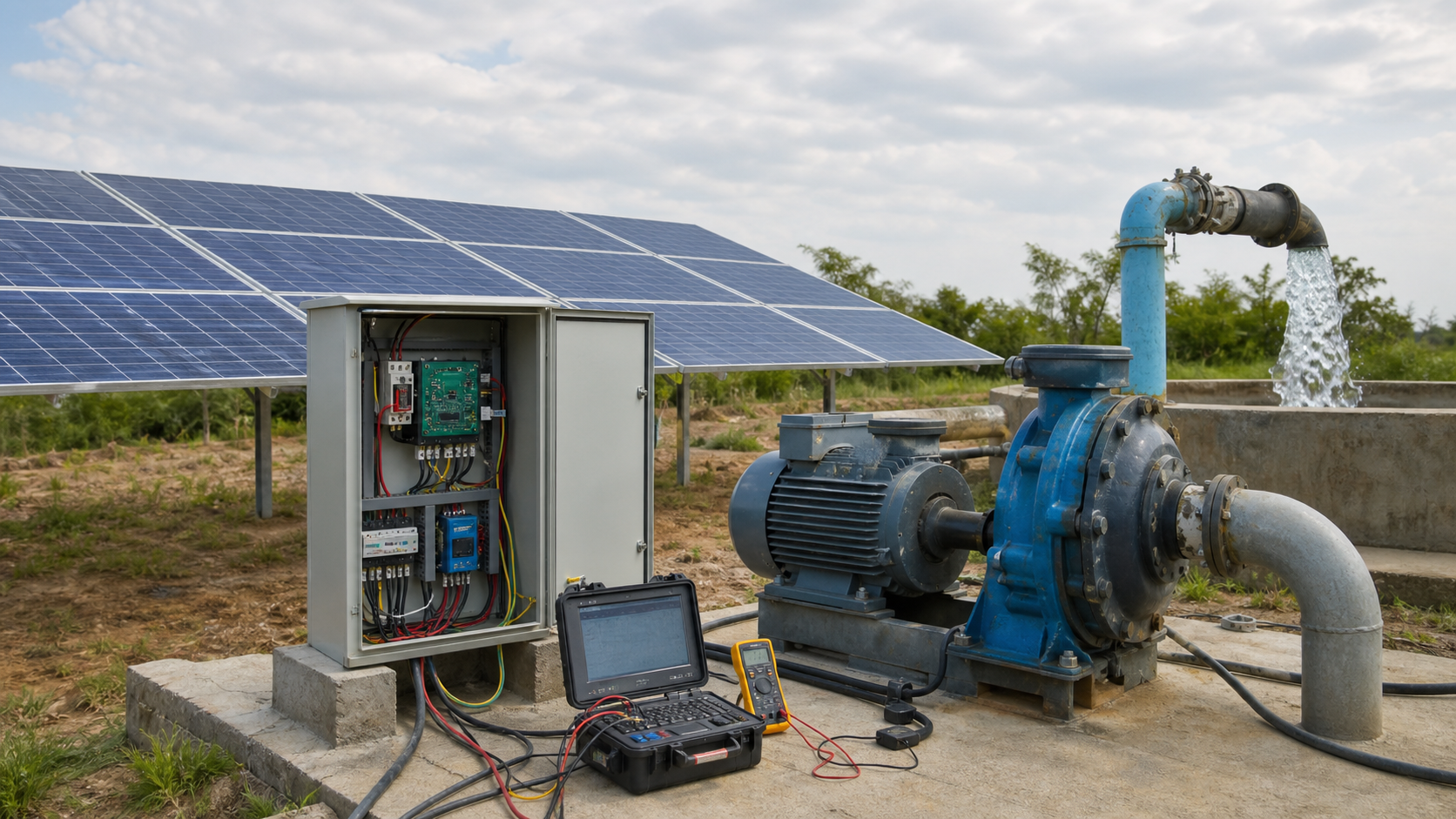
On a partly cloudy morning, your photovoltaic array delivers varying voltage and current as shadows move across panels. Without maximum-power-point tracking, a fixed-voltage converter accepts whatever the array offers, often capturing substantially less than rated capacity. The pump motor turns slowly or stalls because input power drops each time cloud blocks panels in a string. An MPPT solar pump controller solves this by measuring array voltage and current in real time, adjusting its DC input impedance to harvest maximum available power, then converting that DC power into variable-frequency AC output matched to motor torque and speed requirements. The selection decision is electrical matching first—aligning controller input voltage window to array string configuration and controller output voltage and frequency range to motor nameplate—followed by hydraulic verification that the pump can meet flow and head at the speeds available solar power permits.
Key Takeaways
- MPPT controllers continuously adjust input impedance to extract maximum power from the PV array as irradiance, temperature, and shading change throughout the day.
- Controller input voltage must span the array’s open-circuit voltage at cold dawn and the maximum-power voltage at peak irradiance; output voltage and frequency must match motor nameplate.
- Series-connected panels multiply voltage; parallel strings multiply current. Match string count and panel count per string to the controller’s DC input window and current rating.
- Low-irradiance startup requires enough panel power to overcome motor inertia, bearing friction, and static head before the pump delivers flow; weak morning or evening sun may produce voltage without useful work.
- Clipping occurs when array capacity exceeds controller input rating; undervoltage occurs when clouds or dirt drop string voltage below the controller’s minimum operating threshold.
- Water storage decouples pumping schedule from instantaneous solar availability and eliminates the need for battery banks in most irrigation and livestock watering applications.
Why a PV Array Has a Moving Maximum-Power Point
A photovoltaic panel’s voltage-current characteristic is not a straight line. At short-circuit, the panel delivers maximum current but zero voltage. At open-circuit, the panel delivers maximum voltage but zero current. Between these extremes lies one combination of voltage and current that produces maximum power—the maximum power point. As irradiance changes, the maximum-power voltage shifts slightly and maximum-power current scales. Temperature also moves the point: voltage decreases as temperature rises, with the magnitude depending on cell chemistry and manufacturer specifications.
When panels are connected in series to form a string, voltages add. When strings are connected in parallel, currents add. A single shaded or dirty panel reduces current through its entire series string, shifting the maximum-power point and reducing total array power. A fixed-voltage DC-DC converter or direct motor coupling operates at a single voltage setpoint, harvesting maximum power only when that setpoint coincidentally matches the array’s momentary maximum-power voltage.
An MPPT solar pump controller continuously measures array voltage V<sub>pv</sub> and current I<sub>pv</sub>, calculates instantaneous power P = V<sub>pv</sub> × I<sub>pv</sub>, and adjusts input impedance to climb toward maximum-power point. The tracking algorithm samples power at small voltage steps, moving impedance up or down to stay near peak power as conditions change.
What the MPPT Stage Measures and Adjusts
The MPPT stage sits between the PV array and the variable-frequency drive section. It measures array voltage and current, calculates power, and adjusts a DC-DC converter’s duty cycle to change the effective load impedance seen by the array. When impedance is too low, array voltage drops and current cannot compensate; when impedance is too high, voltage rises but current falls. The controller seeks the impedance that yields maximum power.
Common tracking algorithms include perturb-and-observe, which nudges voltage and observes whether power increases, and incremental conductance, which compares the derivative of power with respect to voltage to determine adjustment direction. Tracking speed varies by controller design, with faster tracking responding better to rapid cloud transients at the cost of more processing and potential oscillation.
The MPPT stage also enforces input voltage limits. If array voltage climbs above the controller’s maximum input voltage—common at dawn when panels are cold and unloaded—the controller stops tracking and waits until voltage drops into the safe window. If array voltage falls below minimum tracking voltage—common at dusk or during heavy overcast—the controller stops delivering power to the motor. These thresholds are fixed by controller hardware and define the array configuration you can use.
From DC Power to Variable-Frequency Motor Output
After the MPPT stage harvests DC power from the array, the controller’s inverter section converts that power into three-phase AC at variable frequency and voltage. The inverter uses pulse-width modulation to synthesize sinusoidal output waveforms, with output frequency controlling motor speed and output voltage magnitude scaling with frequency to maintain roughly constant volts-per-hertz ratio.
For a centrifugal pump, flow rate scales proportionally with motor speed, and head scales with the square of speed according to affinity laws. As available solar power decreases, the controller reduces frequency to keep motor within its current limit, and pump output falls. The system curve—static head plus friction loss—remains fixed, so the pump operates at a different duty point each time speed changes.
The inverter must supply sufficient starting torque to overcome static head and accelerate the water column. A pump lifting water vertically requires torque to spin the impeller against that static head before any flow occurs. If solar power is marginal—early morning or thin overcast—the controller may produce voltage and frequency but insufficient torque, causing the motor to hum without turning or turn slowly without delivering flow. Motor current drawn during this condition can approach locked-rotor current, and extended operation at stall or very low speed may overheat the motor if thermal protection is not correctly configured.
Voltage Window, Array String, and Motor Matching
Controller input voltage window defines how many panels you can connect in series. Consult the panel datasheet for open-circuit voltage at the coldest expected temperature and maximum-power voltage at peak irradiance under the hottest expected conditions. Calculate total string voltage by multiplying per-panel voltage by the number of panels in series. The result must remain within the controller’s specified input voltage range across all operating conditions.
For example: A controller with a 200 to 400 VDC input window requires array open-circuit voltage below 400 V at coldest temperature and maximum-power voltage above 200 V at peak irradiance. If a panel’s datasheet shows 48 V open-circuit voltage at standard test conditions with a temperature coefficient of −0.3%/°C, open-circuit voltage at −10°C becomes 48 V × [1 + 0.003 × (−10 − 25)] = 53 V. Ten such panels in series yield 530 V open-circuit cold, exceeding the 400 V limit. Nine panels yield 477 V cold—within the window if maximum-power voltage at hot conditions stays above the 200 V minimum.
Controller input current rating must exceed the array’s short-circuit current at peak irradiance. If each panel produces I<sub>sc</sub> short-circuit current and you connect N strings in parallel, the controller must handle N × I<sub>sc</sub>. Check the controller datasheet for any required margin above calculated short-circuit current.
Controller output voltage and frequency must match motor nameplate. A 230 V three-phase motor requires a controller with 230 V output; a 400 V motor requires 400 V output. Mismatch causes either insufficient starting torque or insulation stress. Motor rated frequency defines base speed for volts-per-hertz ratio.
Pump power requirement at the intended duty point determines controller power rating. Read brake horsepower or kilowatts from the pump curve at required flow and head. The controller must supply at least this power, and the array must deliver enough to cover MPPT and inverter conversion losses.
Startup, Low Irradiance, and Cloud Transients
Pump startup demands higher torque than steady-state operation. The motor must overcome bearing friction, accelerate the rotating assembly, and establish flow against static head and check-valve cracking pressure. If the controller attempts startup at insufficient irradiance, input power may be too low to deliver starting torque, or voltage may drop below minimum tracking threshold as motor draws inrush current. Some controllers implement soft-start algorithms that ramp frequency gradually to limit inrush, but if available power cannot sustain even soft-start torque, the pump will not begin pumping.
Startup irradiance threshold varies with motor size, static head, and pump design. Consult the controller’s documentation or measure actual startup power under known irradiance to establish the minimum operating point. Below this threshold, the controller may connect and disconnect repeatedly as voltage oscillates around minimum tracking point.
Cloud transients cause rapid swings in array current. A controller with fast MPPT tracking will adjust to maintain maximum power, but motor inertia smooths the mechanical response. The pump does not stop each time a cloud passes; kinetic energy in the rotating impeller and water column sustains flow briefly. Repeated transients over seconds or minutes result in variable flow and head, which is acceptable for irrigation and livestock watering but may be problematic for applications requiring steady pressure.
Battery-free solar water pump MPPT systems rely on water storage to decouple supply variability from demand. The pump runs when solar power is sufficient, filling a tank or reservoir. Users draw from storage at any time, independent of weather. This eliminates the cost, maintenance, and disposal burden of battery banks while providing functional reliability equivalent to a grid-connected system for applications that can tolerate storage-based delivery.
Water Storage versus Battery Storage
Direct solar pumping without batteries trades electrical storage for hydraulic storage. An elevated tank or pressurized bladder tank stores potential energy that can be released on demand. Battery storage adds cost, cycle life limits, thermal management requirements, and eventual disposal. For irrigation, livestock watering, and domestic supply in locations where water storage is feasible, battery-free operation simplifies the system and reduces lifetime cost.
Battery storage becomes necessary when water storage is impractical—for example, fire suppression systems requiring instant high-pressure flow, or industrial processes demanding continuous circulation. In these cases, the battery bank buffers the variable solar input and the controller charges batteries while simultaneously running the pump if power permits, or runs the pump from battery reserve when solar power is insufficient.
Hybrid MPPT pump inverter designs accept both DC solar input and AC grid or generator input, switching automatically based on availability. During sunny periods, solar power drives the pump and may export excess energy to the grid or a secondary load. During cloudy periods or nighttime, grid or generator power takes over. This configuration suits operations where downtime is costly but full battery autonomy is not justified.
Diagnose Clipping, Undervoltage, and Weak Output
Clipping occurs when array output exceeds controller input rating. The MPPT stage cannot harvest more power than the controller’s DC-DC converter can handle, so excess capacity is wasted. If your array’s rated capacity exceeds the controller’s input power rating, output will plateau at the controller’s limit even during peak irradiance. Whether clipping is acceptable depends on local irradiance patterns and the economic value of lost energy.
Undervoltage shutdown happens when array voltage drops below controller minimum tracking threshold. Causes include undersized array, excessive cable voltage drop, shading, dirt accumulation, or panel degradation. If the system pumped reliably but now shuts down on partly cloudy days, measure open-circuit voltage and short-circuit current at controller terminals under known irradiance and compare to panel datasheet values. Voltage significantly below expected indicates either cable loss or panel fault; current significantly below expected indicates shading or degradation.
Weak output—pump runs but delivers low flow—can result from incorrect motor frequency limit, air binding, worn impeller, or check valve partially closed. Verify controller frequency output with a clamp meter or display readout. If frequency reaches expected value but flow remains low, the problem is hydraulic or mechanical, not electrical. If frequency is limited even at peak irradiance, check controller configuration and confirm that available solar power meets pump requirement at full speed.
Persistent faults require datalogger review. Many controllers record daily energy, voltage, current, frequency, and fault codes. Compare logged maximum power to expected array output calculated from panel ratings and measured irradiance. If logged maximum consistently falls below rated array capacity, investigate panel condition, wiring integrity, and MPPT calibration. If logged maximum matches expected but runtime is short, the issue is likely low irradiance duration or high static head reducing the useful operating window.
MPPT Controller Matching Checklist
Use this sequence when selecting a controller for a known pump and array:
- Confirm motor voltage and rated frequency. Controller output must match motor nameplate exactly.
- Calculate pump power at duty point. Use the pump curve to find brake horsepower or kilowatts at required flow and head. This establishes minimum controller power rating; add margin per manufacturer recommendation or system design practice.
- Determine array configuration. Count the number of panels per series string to fit within controller’s DC input voltage window. Multiply string count to meet current rating and power requirement.
- Verify voltage window compliance. Calculate array open-circuit voltage at coldest expected ambient temperature using panel datasheet values and temperature coefficients. Confirm it remains below controller maximum input voltage. Calculate maximum-power voltage at peak irradiance and hottest expected temperature and confirm it exceeds controller minimum tracking voltage.
- Check startup irradiance threshold. Consult controller documentation or measure startup power to confirm the pump can start at the lowest acceptable irradiance level for your application.
- Plan water storage capacity. For battery-free operation, size the storage tank or reservoir to cover periods when solar power is insufficient, based on local weather patterns and acceptable service interruption. Consult site-specific consumption data and historical irradiance records.
- Confirm cable sizing. Use conductor ampacity tables, distance, and calculated current to select appropriate cable gauge. Verify that voltage drop remains within controller manufacturer’s recommendation at maximum current.
- Verify controller protections. Confirm that over-temperature, over-current, under-voltage, and dry-run protections are present and that thresholds are configurable or appropriate for pump and motor type.
FAQs
Can I use an MPPT controller with a single-phase motor?
Most MPPT solar pump controllers produce three-phase output. Single-phase motors require a controller specifically designed for single-phase output or a phase converter between controller and motor. Verify output phase count and voltage in controller specifications before purchase.
What happens if I connect more panels than the controller input current rating?
The controller will limit input current to its rated maximum, and the MPPT algorithm will operate at a voltage-current combination that keeps input current below the limit. Excess panel capacity is wasted, and the array operates away from its true maximum power point. In extreme cases, the controller may shut down on over-current fault. Always match total array short-circuit current to controller’s input current rating plus any recommended margin.
Do I need a controller with grid or generator input if I already have water storage?
No. If water storage is sufficient to cover nighttime and cloudy-day demand, a solar-only controller is adequate. Hybrid controllers with grid or generator input are useful when storage is impractical, when the pumping application cannot tolerate downtime, or when local regulations require backup power for fire protection or municipal supply.
How do I prevent the pump from running dry when the well or reservoir level drops?
Install a low-level float switch or pressure transducer in the suction source and wire it to the controller’s external stop input. Most controllers accept a dry-contact input that halts operation when open or closed, depending on configuration. Running a centrifugal pump dry for more than a few seconds can damage the mechanical seal and bearings.
Can I add more panels later to increase pumping capacity?
Yes, if the additional panels keep total array voltage and current within controller’s input window. Adding panels in parallel increases current without changing voltage; adding panels in series increases voltage without changing current. Recalculate open-circuit voltage at cold temperature and maximum-power current at peak irradiance using panel datasheet values to confirm compliance before connecting additional panels.
Conclusion
An MPPT solar pump controller bridges the variable electrical output of a photovoltaic array to the fixed voltage and frequency requirements of a pump motor, continuously adjusting input impedance to harvest maximum available power and converting that power into variable-speed motor drive. Successful matching depends on aligning controller input voltage window to array string configuration, controller output voltage and frequency to motor nameplate, and total system power rating to pump’s brake horsepower at required duty point. Measure your pump’s actual operating flow, head, and power draw; confirm motor nameplate voltage and frequency; calculate array open-circuit voltage at local minimum temperature and maximum-power voltage at peak irradiance using panel datasheet specifications; then select a controller whose ratings span those values. If you need assistance verifying controller compatibility with an existing pump and motor or sizing an array for a planned installation, gather the pump curve, motor nameplate photo, site irradiance data, and panel datasheet before requesting a technical review.