
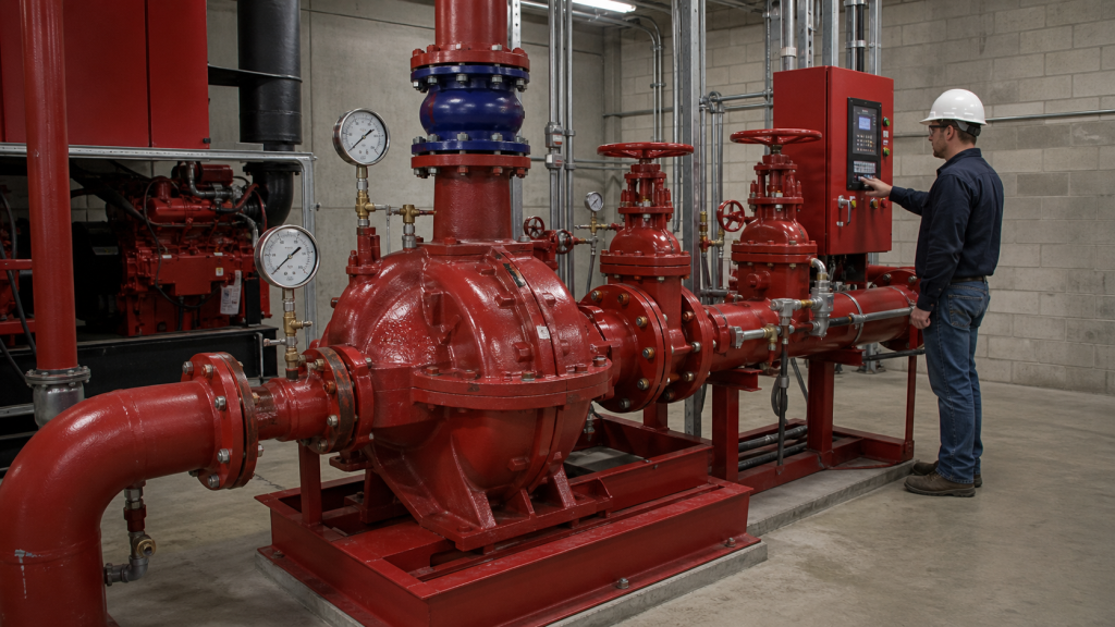
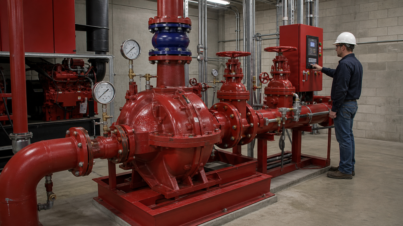
When a fire pump runs at zero discharge flow, the pressure at its outlet reaches maximum. This condition—called churn or shutoff—produces a differential head you can read directly from the certified pump curve, but the absolute pressure at discharge depends on what pressure already exists at suction. Separate the pump’s contribution from the system’s baseline, then confirm that the resulting churn pressure stays within component ratings, controller settings, and relief-valve thresholds. A safe fire-protection system requires that every valve, fitting, flange, pipe, and pump casing can withstand this no-flow pressure without damage or nuisance trips.
Key Takeaways
- Churn pressure equals pump shutoff head (in feet or meters) converted to psi or bar, plus suction pressure.
- The certified pump curve provides shutoff head; field measurements confirm suction pressure and actual discharge pressure during a no-flow test.
- Component and piping ratings must exceed churn pressure; relief valves are required when the total pressure at shutoff exceeds safe limits.
- Controller start settings and jockey pump cutoff points interact with churn: if the jockey maintains pressure near the fire pump’s automatic-start threshold, the fire pump may cycle unnecessarily during a churn test.
- Deviations from the certified curve signal wear, air entrainment, impeller damage, or incorrect speed; always compare test results to the manufacturer’s original data.
What Churn Means on a Fire Pump Curve
Fire pump performance curves plot total dynamic head against flow rate. At the left edge—zero flow—the curve reaches its highest point, labeled shutoff head or churn head. This value represents the maximum pressure rise the pump can deliver when all discharge valves are closed and liquid recirculates internally or remains static inside the casing.
Churn is not an operating point. Fire pumps are sized to deliver rated flow at rated head, and continuous operation at shutoff overheats the liquid, overloads the driver, and accelerates wear. However, churn pressure appears during commissioning tests, maintenance checks, and transient events such as a sudden valve closure. The pump must survive these moments without rupturing pipes, blowing gaskets, or tripping the controller on high pressure.
Certified fire pump curves are tested and documented according to recognized standards. The curve supplied by the manufacturer includes shutoff head as a percentage of rated head. The exact ratio depends on impeller design, specific speed, and curve steepness; consult the pump’s certified performance data.
Convert Shutoff Head to Differential Pressure
Pump curves express performance in head—feet or meters of liquid column—because head is independent of liquid density. To find the corresponding pressure rise across the pump, apply the hydrostatic conversion:
ΔP (psi) = H (ft) × SG × 0.433
or in SI units:
ΔP (bar) = H (m) × SG × 0.0981
where:
- ΔP is the differential pressure rise produced by the pump
- H is the head from the pump curve (shutoff head in this case)
- SG is the specific gravity of the liquid (1.0 for water at standard conditions)
Example Calculation:
A horizontal split-case fire pump has a certified shutoff head of 285 feet when pumping water (SG = 1.0). Convert this to differential pressure:
ΔP = 285 ft × 1.0 × 0.433 = 123.4 psi
This 123.4 psi is the pressure increase the pump adds to whatever pressure already exists at its suction flange. It is not the absolute discharge pressure.
Assumptions:
- Water temperature near 60°F; specific gravity remains 1.0.
- Gauge pressures; atmospheric reference cancels in differential calculations.
- No significant vapor pressure or dissolved gas effects.
If the liquid temperature or composition changes, recalculate specific gravity and confirm that vapor pressure does not approach suction pressure—though fire pumps typically operate with positive suction pressure and cold water.
Add Suction Pressure to Estimate Discharge Pressure
Absolute discharge pressure during churn is the sum of suction pressure and the differential pressure rise:
P_discharge,churn = P_suction + ΔP_pump,shutoff
Suction pressure may be positive (from an elevated tank, municipal supply, or booster pump) or slightly negative (suction lift from a reservoir below the pump). Most fire pump installations use positive suction to ensure reliable priming and meet net positive suction head requirements.
Worked Example:
Continuing the previous case:
- Shutoff head: 285 ft → ΔP_pump = 123.4 psi
- Suction pressure (gauge): 25 psi from a ground-level storage tank
P_discharge,churn = 25 psi + 123.4 psi = 148.4 psi (gauge)
This is the pressure the discharge piping, check valve, control valves, and sprinkler system must withstand when the pump runs at zero flow. Compare this value to:
- Pipe and fitting pressure ratings (ANSI class, schedule, or material specification)
- Check valve body and seat ratings
- Sprinkler system design pressure and test pressure
- Relief valve set point, if installed
System design must account for pressure at churn, not just at rated flow.
Compare Churn with Component and System Ratings
Every component downstream of the pump must tolerate churn pressure. Verify ratings against actual installation materials and confirm adequate safety margin.
Comparison checklist:
- Piping and fittings: Confirm the pressure class or schedule matches or exceeds churn pressure.
- Check valve: Body rating must exceed churn; seat tightness under shutoff pressure prevents backflow.
- Control valves and isolation valves: OS&Y gate valves or butterfly valves on the discharge side see full churn pressure when closed.
- Sprinkler heads and system test connection: Design pressure is typically lower than churn; the system is not pressurized to churn during normal standby, but transient events can produce momentary spikes.
- Pump casing and flanges: Certified fire pumps are hydrostatically tested at the factory, but field modifications or incorrect gaskets can introduce weak points.
When churn pressure approaches or exceeds safe limits, a relief valve is mandatory. Fire pump relief valves are sized and set according to specific rules for centrifugal and diesel-driven units. For a diesel-engine-driven pump, the relief valve is required when 121 percent of net rated shutoff pressure plus maximum static suction pressure exceeds the component rating. The valve discharges back to the suction source or to waste, preventing overpressure while the pump runs at churn.
Electric motor-driven pumps follow a similar logic but with different thresholds. Always consult the pump manufacturer’s installation manual and the applicable fire protection standard for your jurisdiction.
Controller Settings and Jockey Pump Interaction
Fire pump controllers start the pump automatically when system pressure drops below a preset threshold that is coordinated with the jockey pump’s operating range. The jockey pump is a small centrifugal pump that compensates for minor leaks and keeps the system pressurized without starting the main fire pump.
During a churn test, the fire pump runs with the discharge valve closed. If the jockey pump is still running and trying to maintain pressure, the two pumps can interact. The jockey pump’s discharge pressure, combined with the fire pump’s shutoff head, may push system pressure higher than expected. To avoid this interference:
- Isolate or stop the jockey pump before conducting a fire pump churn test.
- Record both suction and discharge pressures independently to confirm the fire pump’s differential contribution.
- Verify that the controller’s high-pressure cutoff (if equipped) does not trip prematurely due to combined pressure from both pumps.
Controller start and stop pressures are adjustable but must remain coordinated with system design pressure and jockey pump operation. If the fire pump starts too close to the jockey’s shutoff point, nuisance starts occur. If it starts too far below, the system may lose pressure before the fire pump responds.
After a churn test, confirm that the controller returns to automatic mode and that pressure transducers or sensing lines are not damaged by the momentary high pressure.
Conduct and Record a No-Flow Test Safely
A churn test demonstrates that the pump can develop its certified shutoff head and that all components tolerate the resulting pressure. The test is part of commissioning and periodic fire pump maintenance schedules.
Basic Churn Test Procedure:
- Verify system readiness: Confirm all suction and discharge isolation valves are open except the discharge test valve. Check that suction supply is available and priming is complete.
- Install or confirm pressure gauges: Place calibrated gauges at the pump suction flange and discharge flange. Gauges must be rated above expected churn pressure.
- Isolate the jockey pump: Prevent interaction by stopping or isolating the jockey pump before starting the fire pump.
- Close the discharge valve slowly: With the pump running, close the valve on the discharge side to bring flow to zero. Monitor pressure rise.
- Record pressures: Note suction pressure (P_suction) and discharge pressure (P_discharge,churn) when flow reaches zero. The differential is the actual shutoff head in pressure units.
- Hold for observation period: Maintain churn for the duration specified in the test protocol and watch for leaks, vibration, or abnormal noise.
- Open the discharge valve: Return flow slowly to avoid water hammer. Stop the pump according to the controller sequence.
- Calculate and compare: Convert measured ΔP back to head if needed, and compare to the certified curve. Record deviations.
Safety considerations:
- Water hammer: Rapid valve closure or opening can produce transient pressures far exceeding static churn. Operate valves smoothly.
- Temperature rise: Extended churn heats the liquid inside the pump casing. Limit test duration to avoid thermal damage.
- Pressure relief: If a relief valve opens during the test, verify its set point and discharge path. Do not plug or override the valve.
- Electrical lockout: Follow site electrical safety procedures when working near motor starters, controllers, and power panels.
Document the test with date, time, personnel, ambient conditions, measured pressures, and any anomalies. This record is required for code compliance and provides a baseline for future comparisons.
Explain Deviations from the Certified Curve
If the measured churn pressure differs significantly from the expected value calculated from the certified curve, investigate the cause. Common reasons include:
Impeller wear or damage: Erosion, cavitation pitting, or impact damage reduces impeller diameter and efficiency, lowering shutoff head. Compare current performance to past test records.
Incorrect impeller trim: Replacement impellers must match the original diameter. An undersized impeller shifts the entire curve downward.
Wrong speed: Fire pumps are rated at a specific RPM. If the driver speed is incorrect (diesel governor setting, motor nameplate error, or VFD misconfiguration), the affinity laws predict a squared relationship between speed and head. A small speed error produces a proportionally larger head error.
Air entrainment: Air leaks in suction piping, a low suction reservoir level, or vortex formation at the inlet reduce effective head and create erratic pressure readings. Inspect suction strainers, flange gaskets, and packing glands for leaks.
Discharge obstruction: A partially closed valve, debris in the piping, or a stuck check valve can raise discharge pressure above expected shutoff, but this is less common since churn testing is done with known valve positions.
Gauge error or placement: Pressure taps too close to the pump or elbows, or uncalibrated gauges, produce false readings. Use calibrated test gauges at the specified tap locations shown on the pump installation drawing.
When measured churn pressure deviates from the certified curve, the pump requires maintenance or adjustment. Always compare to the same reference: ensure the certified curve and field test both use the same liquid, temperature, and gauge datum.
Churn-Pressure Review Worksheet
Use this checklist during commissioning, after maintenance, or when investigating system pressure issues.
Item | Value / Status | Notes |
|---|---|---|
Certified shutoff head (ft or m) | From pump nameplate or certified curve | |
Specific gravity | Typically 1.0 for water | |
Calculated ΔP_pump (psi or bar) | H × SG × 0.433 (or 0.0981 SI) | |
Measured suction pressure (gauge) | During churn test | |
Expected discharge pressure (gauge) | P_suction + ΔP_pump | |
Measured discharge pressure (gauge) | During churn test | |
Deviation from expected (%) | (Measured – Expected) / Expected × 100 | |
Discharge piping rating | ANSI class, schedule, or material spec | |
Check valve body rating | From valve nameplate | |
Relief valve present? | Yes / No | Required when churn exceeds limits |
Relief valve set point (psi or bar) | Must be below component rating | |
Jockey pump isolated during test? | Yes / No | Prevents pressure interaction |
Test duration (seconds) | Limit to avoid overheating | |
Vibration or noise observed? | Yes / No | Investigate if abnormal |
Pass / Fail | Pass criteria per site protocol |
Retain this worksheet with the fire pump maintenance log and provide a copy to the authority having jurisdiction during inspections.
FAQs
What is the difference between shutoff pressure and churn pressure?
Shutoff pressure and churn pressure are often used interchangeably, but technically shutoff head is the value from the pump curve, while churn pressure is the absolute pressure measured at the discharge flange during zero flow. Churn pressure equals shutoff head (converted to pressure units) plus suction pressure.
Can a fire pump run continuously at churn without damage?
No. Continuous operation at churn overheats the liquid, causing thermal expansion, vaporization, and accelerated wear of seals, bearings, and impellers. Churn tests are limited to brief durations specified in the test protocol. If the pump must run with no discharge flow due to a system fault, install a recirculation line or relief valve to prevent damage.
Why does my churn pressure exceed the rated pressure of the sprinkler system?
Fire sprinkler systems are designed for a working pressure at rated flow, not at shutoff. During normal operation, flow through the system drops pressure due to friction losses, so the sprinkler heads see less than the pump’s full discharge pressure. At churn, with valves closed, the full shutoff pressure appears in the piping near the pump. This is why component ratings near the pump must exceed churn pressure, even if downstream devices are rated lower.
How do I size a relief valve for a fire pump?
Relief valve sizing depends on the pump’s rated flow, shutoff head, and driver type. Consult the manufacturer’s installation manual and applicable standards. The valve must open at or below the maximum allowable pressure and discharge enough flow to prevent pressure from rising further. Relief valve placement and discharge piping are also specified in fire protection codes.
What should I do if my churn test shows lower pressure than the certified curve?
First, verify gauge calibration and test procedure. If the reading is accurate, check pump speed (RPM for diesel engines, motor nameplate for electric drives), inspect the impeller for wear or damage, and look for air leaks in the suction piping. Compare the current test to previous records to identify trends. Persistent low performance requires impeller replacement, speed correction, or pump overhaul.
Conclusion
Fire pump churn pressure is the sum of the pump’s differential shutoff head and the existing suction pressure. It defines the maximum pressure the discharge system must tolerate and guides relief valve selection, component ratings, and controller settings. To verify churn pressure, compare the measured no-flow discharge pressure during a field test to the value calculated from the certified pump curve, adjusted for actual suction conditions. If the measured result deviates from the expected value, investigate speed, impeller condition, air entrainment, or gauge accuracy before returning the pump to service. Keep a completed churn-pressure review worksheet in the maintenance file, and confirm that all piping, valves, and fittings downstream of the pump can withstand the churn pressure without failure.