
title: "Pump Head Calculation: Formula, Units, and Worked Examples"
description: "Learn the formula, units, assumptions, and a worked example, then see how to avoid common pump calculation errors in real industrial systems."
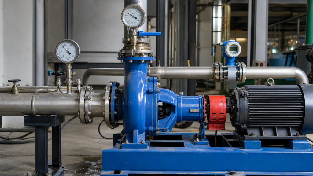
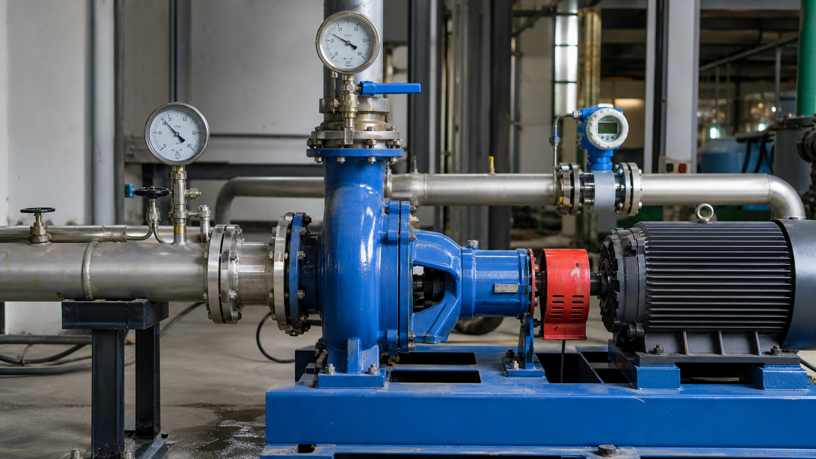
Two pressure gauges on a pump—one on the suction flange reading 20 psi, another on the discharge flange 5 feet higher reading 80 psi—might suggest the pump head is 60 psi. That answer is incomplete. The elevation difference between gauges matters, velocity at each measurement point matters, and converting pressure to head requires the liquid density. Miss any of these factors and your calculated head will disagree with the manufacturer’s curve by enough margin to select the wrong pump or misdiagnose a performance problem.
Pump head calculation determines the energy per unit weight that a pump imparts to the liquid, expressed in length units such as feet or meters. It combines pressure differences, elevation changes, and velocity changes into a single dimension that matches published pump curves. This article walks through the general energy equation, explains datum point selection, demonstrates a complete gauge-to-gauge calculation with units, and identifies where sign errors and unit confusion most often occur.
Key Takeaways
- Pump head is energy per unit weight delivered to the liquid, expressed in feet or meters, not pressure units.
- The general energy equation accounts for pressure, elevation, and velocity head at both suction and discharge measurement points.
- Converting gauge pressure to head requires dividing by the liquid’s specific weight (density × gravity).
- Elevation differences between gauge locations must be included in the calculation to isolate the pump’s contribution.
- Calculated head must match the units on the pump curve before selecting a duty point or checking performance.
- Common errors include ignoring velocity head, mixing pressure and head units, reversing elevation signs, and assuming water density at the wrong temperature.
What Pump Head Measures
Pump head quantifies how much energy the pump adds to each pound or kilogram of liquid passing through it. Unlike pressure, which depends on liquid density and varies with temperature or composition, head measures potential energy change and remains constant for a given pump operating at fixed speed and flow rate regardless of the pumped liquid’s density.
When you read 100 feet of head on a pump curve, the same impeller and casing at the same speed will lift water 100 feet vertically or raise gasoline 100 feet or boost light oil 100 feet—even though the discharge pressure in psi will differ for each liquid because their densities differ. Pump curves are published in head units because the pump’s hydraulic geometry determines head; the system and liquid properties then determine the resulting pressure.
Engineers calculate pump head to match the pump’s published performance curve with the actual system requirement. The calculated value becomes the vertical coordinate on the curve, allowing you to confirm the pump can deliver the required flow at the system’s operating point.
Choose Suction and Discharge Datum Points
Before calculating head, define where you will measure suction conditions and discharge conditions. These are your datum points. Typical choices include:
- Gauge-to-gauge: Pressure gauges on the pump suction and discharge flanges. This is the most direct method for field verification but requires attention to gauge elevation differences.
- Tank-to-tank: Liquid surface in the suction tank or reservoir and liquid surface in the discharge tank. Useful for system design when the pump location is not yet fixed.
- Closed-loop systems: Any convenient point in the loop where you can define suction and discharge reference pressures, such as at a heat exchanger inlet and outlet.
The datums do not need to be at the pump centerline, but you must measure or calculate pressure, elevation, and velocity at each datum consistently. Changing datum points mid-calculation or mixing gauge readings from different elevations without accounting for the elevation difference will produce incorrect results.
Pump Head Formula from the Energy Equation
The general energy equation between two points in a flowing system gives:
H = (P₂/γ + z₂ + v₂²/2g) − (P₁/γ + z₁ + v₁²/2g)
Where:
- H = pump head (ft or m)
- P₂ = discharge pressure absolute (lb/ft² or Pa)
- P₁ = suction pressure absolute (lb/ft² or Pa)
- γ = specific weight of liquid (lb/ft³ or N/m³)
- z₂ = elevation of discharge datum (ft or m)
- z₁ = elevation of suction datum (ft or m)
- v₂ = liquid velocity at discharge datum (ft/s or m/s)
- v₁ = liquid velocity at suction datum (ft/s or m/s)
- g = gravitational acceleration (32.2 ft/s² or 9.81 m/s²)
Each term has units of length. P/γ is pressure head, z is elevation head, and v²/2g is velocity head. The pump head H is the difference in total energy head between discharge and suction.
If you are working with gauge pressures instead of absolute pressures, the atmospheric pressure terms cancel out:
H = (P₂,gauge/γ + z₂ + v₂²/2g) − (P₁,gauge/γ + z₁ + v₁²/2g)
This form is more common in field measurements because most pressure gauges read gauge pressure (psig or barg) rather than absolute pressure.
Convert Pressure Difference to Head with Density
Pressure gauges report force per unit area, but pump curves use length units. The conversion factor is the liquid’s specific weight γ, which equals density ρ times gravitational acceleration g.
For water at 68°F (20°C), the density is approximately 62.4 lb/ft³ or 1,000 kg/m³. If you measure a pressure difference of 43.2 psi, the equivalent head in feet of water is:
Convert psi to lb/ft²: 43.2 psi × 144 in²/ft² = 6,220.8 lb/ft²
Divide by specific weight: 6,220.8 lb/ft² ÷ 62.4 lb/ft³ = 99.7 ft
Or use the conversion for water at standard conditions: 1 psi ≈ 2.31 ft of head, so 43.2 psi × 2.31 ft/psi ≈ 99.8 ft.
If the liquid is not water at 20°C, use the actual density. Hot water at 180°F has a density of approximately 60.6 lb/ft³, so the same 43.2 psi corresponds to 6,220.8 ÷ 60.6 = 102.7 ft. Ignoring the temperature correction introduces a 3% error in this case.
For liquids other than water, express density as specific gravity (SG) relative to water and adjust the conversion factor. A liquid with SG = 0.85 will show higher head than water for the same pressure difference: 43.2 psi ÷ 0.85 ≈ 117.4 ft.
Worked Gauge-to-Gauge Calculation
A centrifugal pump moves water at 68°F. The suction gauge, installed 1.5 ft below the pump centerline, reads 5 psig. The discharge gauge, installed 2.0 ft above the pump centerline, reads 78 psig. Suction pipe diameter is 6 inches; discharge pipe diameter is 4 inches. Flow rate is 500 gpm. Calculate the pump head.
Step 1: Calculate velocities
Suction velocity:
v₁ = Q / A₁ = (500 gpm × 0.002228 ft³/s per gpm) / (π × (3 in / 12)² / 4) = 1.114 / 0.196 = 5.68 ft/s
Discharge velocity:
v₂ = Q / A₂ = 1.114 / (π × (2 in / 12)² / 4) = 1.114 / 0.087 = 12.8 ft/s
Step 2: Calculate velocity heads
v₁² / 2g = (5.68)² / (2 × 32.2) = 0.50 ft
v₂² / 2g = (12.8)² / (2 × 32.2) = 2.54 ft
Step 3: Set datum elevations
Taking the pump centerline as elevation zero:
z₁ = -1.5 ft (suction gauge is 1.5 ft below centerline)
z₂ = +2.0 ft (discharge gauge is 2.0 ft above centerline)
Step 4: Convert pressures to head
P₁ / γ = (5 psig × 144) / 62.4 = 11.54 ft
P₂ / γ = (78 psig × 144) / 62.4 = 180.0 ft
Step 5: Apply the energy equation
H = (180.0 + 2.0 + 2.54) − (11.54 − 1.5 + 0.50)
H = 184.54 − 10.54 = 174 ft
The pump delivers 174 feet of head at 500 gpm. You would now locate this operating point on the manufacturer’s curve to verify it falls within the preferred operating range and check that the required power and NPSH are acceptable.
Subtracting gauge readings alone (78 − 5 = 73 psi ≈ 169 ft) would underestimate the head by 5 feet because it ignores the elevation difference and velocity head change.
Tank-to-Tank and Closed-Loop Cases
When the suction and discharge datums are liquid surfaces in open tanks, the pressure at each surface is atmospheric and the gauge pressures are both zero. The velocity at each surface is also typically negligible if the tank area is much larger than the pipe area. The energy equation simplifies to:
H = z₂ − z₁
This is the static lift: the vertical distance from the suction liquid surface to the discharge liquid surface. Total system head adds friction losses and minor losses in the piping, valves, and fittings to this static lift, but the pump head calculation itself measures only what the pump contributes, not what the system requires.
In a closed-loop system such as a chilled water circuit, the suction and discharge datums might be at the same elevation. If you measure pressures at the inlet and outlet of a heat exchexchanger at the same height and the pipe sizes are equal, z₂ = z₁ and v₂ = v₁, so:
H = (P₂ − P₁) / γ
The pump head equals the pressure rise across the pump converted to length units. This is the simplest case but applies only when elevation and velocity contributions are negligible.
Common Unit, Sign, and Datum Errors
Mixing head and pressure: Pump curves show head in feet or meters. Comparing a calculated pressure in psi directly to the curve without converting to head will put you on the wrong part of the curve. Always convert pressure to head using the correct liquid density.
Reversing elevation signs: Elevation terms are z₂ − z₁, so if the discharge gauge is 3 feet higher than the suction gauge, you add 3 feet to the discharge side. A common mistake is to subtract the elevation difference from the head instead of adding it.
Ignoring velocity head: If the discharge pipe is smaller than the suction pipe, the velocity head increases. Neglecting this term can underestimate pump head by several feet in high-flow systems. Velocity head is small in large-diameter low-velocity systems but can exceed 5 feet in compact high-velocity designs.
Wrong density or temperature: Using 62.4 lb/ft³ for hot water or glycol mixtures gives incorrect head. Always confirm the liquid temperature and composition, then look up or calculate the actual density.
Gauge vs. absolute pressure: The energy equation works with either gauge or absolute pressures as long as you use the same basis on both sides. Mixing gauge and absolute pressures without correcting for atmospheric pressure introduces a 34-foot error in water systems at sea level.
Moving datums mid-calculation: If you define the suction datum at a tank surface and the discharge datum at a gauge on the pump, you must include all the elevation and velocity changes between those two points. Switching reference points partway through breaks the energy balance.
Use Calculated Head on the Pump Curve
Once you have calculated the pump head in feet or meters, locate that value on the vertical axis of the manufacturer’s pump curve. Read horizontally to find where it intersects the curve at your flow rate. This operating point shows the pump’s efficiency, required power, and net positive suction head required (NPSHr) at your actual duty.
If the calculated head is higher than the pump can deliver at your flow rate, the pump is undersized. If the calculated head is much lower than the shutoff head, you are operating far to the right of the best efficiency point (BEP) and may encounter cavitation, recirculation, or excessive power draw.
Compare the calculated head to the system curve if you are designing a new installation. The system curve shows how required head increases with flow rate due to friction losses. The pump curve shows how delivered head decreases with flow rate due to hydraulic losses in the impeller. The intersection of the two curves is the stable operating point.
For field verification, measure the actual gauge pressures, elevations, and flow rate, then calculate the head and compare it to the curve at the measured flow. A shortfall from the curve may indicate wear, impeller damage, air entrainment, or incorrect impeller diameter. Document the measured values, calculated head, and curve comparison in your maintenance records so trends become visible over time.
FAQs
What is the difference between pump head and total dynamic head?
Pump head is the energy the pump imparts to the liquid, measured from suction flange to discharge flange (or other chosen datums) using the energy equation. Total dynamic head (TDH) is the total system requirement including static lift, friction losses, and pressure requirements. The pump must deliver head equal to or greater than the TDH for the system to operate at the desired flow rate. Pump head is what the pump does; TDH is what the system needs.
Can I calculate pump head without measuring velocity?
Yes, if the suction and discharge pipe diameters are equal and the measurement points are at the same elevation, velocity head cancels out and you can calculate head from the pressure difference alone: H = (P₂ − P₁) / γ. However, if pipe sizes differ or gauges are at different heights, neglecting velocity head and elevation head will produce incorrect results. Whether velocity head can be safely neglected depends on the specific system velocities and the accuracy required for your application.
How do I calculate pump head if I only have tank levels and no pressure gauges?
Measure the vertical distance from the suction liquid surface to the discharge liquid surface. That distance is the static head. If the tanks are open to atmosphere and large enough that surface velocities are negligible, the pump head for zero flow (shutoff) equals the static head. At higher flows, the pump must also overcome friction and minor losses, so actual pump head equals static head plus system losses. This becomes a system calculation that belongs in the total dynamic head workflow rather than a pure pump head calculation.
Does pump head change if I switch from water to a heavier liquid?
No. Pump head in feet or meters remains the same for a given impeller at a given speed and flow rate, regardless of liquid density. The discharge pressure in psi or bar will increase proportionally to the density, and the power required will also increase, but the head stays constant. This is why manufacturers publish curves in head units rather than pressure units. Always calculate head using the actual pumped liquid’s density, not water’s density.
How do I calculate pump head in a system with multiple pumps in series?
Each pump in series adds its head to the total. If two identical pumps are in series, the combined head at a given flow rate is twice the head of a single pump. Measure the pressure and elevation at the inlet of the first pump and at the outlet of the last pump, then apply the energy equation across the entire series. The calculated head is the total delivered by all pumps combined. To find the head contributed by each individual pump, you must measure conditions between stages.
Conclusion
Pump head calculation gives you a measured or predicted operating point in the same units as the manufacturer’s performance curve, allowing you to verify correct selection, diagnose performance loss, and document operating conditions. Start by defining clear suction and discharge datums, measure or calculate pressure, elevation, and velocity at each point, apply the energy equation with correct units and signs, and convert the result to feet or meters of head before comparing to the curve. The next step is to pull the actual test curve from the manufacturer, mark your calculated operating point, and confirm that efficiency, power, and available NPSH margin support reliable long-term operation at that duty.